Assessing Polar Alignment
|

|
The Accurate Polar Alignment feature (page 501) uses the TPoint model to determine the polar alignment error, then offset slews a star so that it can be re-centered using the mount’s mechanical polar alignment adjustments.
Accurate Polar Alignment methods is preferable to using the polar alignment report, as mechanical hysteresis may result in less-than-ideal polar alignment.
|
After collecting six to ten pointing samples, use the Polar Alignment tab on the TPoint Module window to assess the mount’s polar alignment. Using the bright stars in a constellation (Ursa Major, for example) works well.
After six pointing samples are collected, the telescope’s pointing accuracy should improve noticeably.
Procedure for Assessing Telescope Calibration and Polar Alignment
1. Accurately set the computer clock each night. Inaccurate time introduces right ascension offset errors.
2. On the TPoint Module window, Setup tab, click TPoint Settings > New.
3. On the Calibration Run tab, click the Start button.
4. Synchronize the telescope on a bright star. When performing a TPoint calibration, synchronize the telescope once for each run. Synchronizing more than once requires a new TPoint model.
5. Click OK on the Start Calibration Run window (page 520).
6. Slew to a nearby star (by identifying the star in TheSky and clicking the Slew button), center the star in the eyepiece, and then click the Add Pointing Sample button. The pointing data now has one pointing sample. After collecting six pointing samples, pointing should greatly improve. Now, you’re ready to collect pointing samples over a larger portion of the actual night sky.
7. After collecting about 20 pointing samples, click the Model tab and add additional terms to the TPoint model so that the RMS value is as small as possible, without increasing the PSD value.
8. Review the suggestions in the polar alignment report by clicking the Polar Alignment tab on the TPoint Module window. Adjust the mount’s polar axis accordingly.

|
Figure 236: Sample Polar Alignment Report.
|
The optimum location of the polar axis depends on what declination and hour angle you’re observing, and your observing goals. For observations on the meridian, somewhere between the true and refracted pole is best. Ideally, one should shoot for the refracted pole.
The TPoint Polar Alignment Report on the Polar Alignment tab makes suggestions to align with the refracted pole automatically. For reference, the table below shows the angular distance (in arcseconds) between the refracted and unrefracted poles for different latitudes and elevations.
|
Angular Distance Between the Refracted and Unrefracted Poles (Latitude vs. Elevation)
|
Latitude (deg.)
|
0m
|
250m
|
500m
|
1000m
|
1500m
|
2000m
|
2500m
|
3000m
|
|
85
|
5
|
5
|
5
|
4
|
4
|
4
|
4
|
4
|
|
80
|
10
|
10
|
9
|
9
|
8
|
8
|
8
|
7
|
|
75
|
15
|
15
|
14
|
14
|
13
|
12
|
12
|
11
|
|
70
|
20
|
20
|
19
|
18
|
17
|
17
|
16
|
15
|
|
65
|
26
|
25
|
25
|
24
|
22
|
21
|
20
|
19
|
|
60
|
32
|
31
|
31
|
29
|
28
|
26
|
25
|
24
|
|
55
|
39
|
38
|
37
|
35
|
34
|
32
|
30
|
29
|
|
50
|
47
|
46
|
45
|
42
|
40
|
38
|
36
|
35
|
|
45
|
56
|
54
|
53
|
50
|
48
|
46
|
43
|
41
|
|
40
|
66
|
65
|
63
|
60
|
57
|
54
|
52
|
49
|
|
35
|
80
|
78
|
76
|
72
|
68
|
65
|
62
|
59
|
|
30
|
96
|
94
|
92
|
87
|
83
|
79
|
75
|
71
|
|
25
|
119
|
116
|
113
|
108
|
102
|
98
|
93
|
88
|
|
20
|
152
|
148
|
145
|
138
|
131
|
125
|
118
|
113
|
|
15
|
205
|
200
|
195
|
185
|
176
|
168
|
160
|
152
|
|
10
|
305
|
298
|
290
|
276
|
263
|
250
|
238
|
227
|
The polar alignment report below is based on a pointing calibration run with 233 points that was acquired using automated pointing calibration (page 508).
This sample pointing data is included with the TPoint module and the report can be reproduced by:
1. Choose the TPoint Module command from the Telescope menu.
2. Choose the Import Pointing Data command from the TPoint Settings pop-up menu on the Setup tab.
3. Choose Burnett.dat and click the Open button.
4. Click the Super Model button on the Model tab and click the Apply button on the Super Model window once the Super Model has been computed.
5. The report below is now displayed on the Polar Alignment Report tab.
Northern Hemisphere Polar Alignment Report
Important information:
· ME is the vertical misalignment of the polar axis of an equatorial mount.
· MA is the misalignment of the polar axis of an equatorial mount to the left or right of the true pole.
· The altitude report shows the adjustments necessary to align with the refracted pole, not the true pole.
Azimuth
Recommendation: Azimuth alignment is excellent. No additional azimuth adjustment is necessary.
Supporting information
MA = -25.5 arcseconds (-0.4 minutes) Sigma = 2.7 - Adjust Confidence-High.
For latitude +30° 12' 49", rotate the azimuth axis East 29.5 arcseconds (0.5 arcminutes).
Altitude
Recommendation: Make the following altitude adjustment...
Supporting information
ME = 43.2 arcseconds (0.7 arcminutes) Sigma = 7.9 - Adjust Confidence-High
'Recommended ME' = -98 arcseconds (the refracted pole).
ME adjustment to get to above 'Ideal ME': 141 arcseconds (2.3 arcminutes).
The polar axis should be raised 141 arcseconds (2.3 arcminutes).
Polar Axis Settings to Satisfy Various Criteria Related to Field Rotation and Unguided Tracking
|
ME
|
MA
|
Description
|
|
+43
|
-25
|
current setting
|
|
-98
|
+0
|
refracted pole, (recommended, same as report above)
|
|
-45
|
+0
|
minimize field rotation
|
|
+166
|
-99
|
minimize unguided declination drift
|
|
+178
|
-112
|
minimize unguided total drift
|
|
+269
|
-93
|
simulated drift method
|
The polar axis is currently 43 arcsec below and 25 arcsec to the left of the true pole.
To reach the refracted pole, (recommended, same as report above) raise the polar axis by 141 arcsec and rotate the mount clockwise by 29 arcsec.
To minimize field rotation, raise the polar axis by 88 arcsec and rotate the mount clockwise by 29 arcsec.
To minimize unguided declination drift, lower the polar axis by 123 arcsec and rotate the mount anticlockwise by 86 arcsec.
To minimize unguided total drift, lower the polar axis by
135 arcsec and rotate the mount anticlockwise by 100 arcsec.
To simulate the drift method, lower the polar axis by
226 arcsec and rotate the mount anticlockwise by 78 arcsec.
As the report describes, for this mount, polar alignment in azimuth is “excellent” (90 arcseconds or less from the refracted pole) and no adjustments are necessary when shooting for the refracted pole. The elevation of the polar axis should be raised 141 arcseconds.
After adjusting the mount’s polar axis, the model can be recalibrated using the portable option (page 501) and produce excellent pointing.
Show Alternative Polar Alignments (Advanced) Checkbox
When the Show Alternative Polar Alignments (Advanced) checkbox is turned on, the polar alignment report includes information about alternative polar alignment techniques; it even shows how to align the polar axis to simulate the results that would be achieved using the drift method for your mount and optical configuration.
|
|
There is no one correct polar axis alignment that makes “everything right.”
Determining the optimal position for the mount’s polar axis with respect to the actual pole is a matter of picking your compromise.
For example, minimizing declination drift is what you might choose if your mount can guide in right ascension, but not in declination. This method was common in antique telescopes where the only method of guiding was to change the clock rate. Minimizing total drift is a good compromise for unguided tracking all over the sky.
The standard recommendation is the refracted pole, which sacrifices a little bit of unguided performance to minimize difficulties when you want to get close to the pole. Observers at low latitudes who rarely try to observe “in the murk” near the pole might be better off with the "minimize total drift" choice.
|
Rough Polar Alignment
The Rough Polar Alignment Procedure described in the Paramount User Guide is available as a wizard. Choose the Rough Polar Alignment command from the Tools menu or click the Rough Polar Alignment button on the Polar Alignment tab, then carefully follow the step-by-step instructions to approximately align the mount with the celestial pole.
Accurate Polar Alignment
After the mount’s mechanical polar axis has been approximately aligned with the celestial pole using the rough polar alignment procedure, the next step is to perform an to collect pointing calibration samples to quantify the mount’s polar misalignment (say, a minimum of 25, acquired on both sides of the meridian). Once complete, from the main menu, click Tools > Accurate Polar Alignment, or click Telescope > TPoint Module > Polar Alignment tab > Accurate Polar Alignment button on the Polar Alignment tab to begin the accurate polar alignment process.
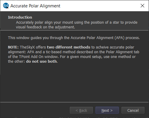
Figure 237: The Accurate Polar Alignment Introduction window.