The Cameras+ Module incorporates many powerful features for autoguiding using CCD, DLSR or video camera.
This chapter describes how to use the Cameras+ Module to autoguide using a camera with dual CCDs from SBIG (essentially two cameras in one, where autoguiding is called Self-Guiding) or autoguide using two independent cameras, one for imaging and one for autoguiding. We typically refer to the imaging camera or "main camera", the one that is capturing the resultant autoguided photo, as the "Imager" and the autoguiding camera as the Autoguider.
Here you will learn how to:
· Determine how well your mount can autoguide.
· How to fine-tune your mount for autoguiding.
· How to use the autoguiding features in the Cameras+ Module effectively.
· How to customize the autoguiding settings to meet your needs.
For this chapter, an experienced user is familiar with autoguiding a mount through software.
One important feature in the Cameras+ Module is the ability to continue autoguiding even after downloading an image. This allows you to take multiple, autoguided photos without restarting autoguiding. The autoguiding process runs independently of the imaging process. In fact, if you have a physically separate, independent autoguider, autoguiding is continuous (with an SBIG dual CCD the imager and autoguider share the same shutter so autoguiding is briefly paused while the imager is downloaded).
Another key feature: since the TheSky Professional with the Cameras+ Module includes a complete framework for star charting and telescope control, the Cameras+ Module offers unsurpassed camera, guider, focuser, filter wheel, rotator, and mount integration.
Before you can autoguide, you must first calibrate the autoguider. Open the Autoguider tab (click Display > Autoguider if the window is not visible), and follow these steps:
1. From the Autoguide tab on the Autoguider window, click Connect.
2. Click Take Photo and use the mount’s motion controls, or the camera's relay buttons, to position a bright calibration star on the autoguider photo, and not near an edge of the photo. For best results, the star should not be saturated and there should not be any stars of similar brightness on the photo so that the bright calibration star can be easily recognized.
3. Click Calibrate. While the calibration is in progress, the autoguider photo shows arrows on the photo to indicate the direction the calibration star moves as each relay is activated (that is, when the mount is moved). If calibration fails due to insufficient guide star movement, click Settings and increase the X and Y calibration times and or check the relay cable from the camera to the mount to make sure it is functioning properly.
4. When calibration is complete, the results are displayed (you can view the results any time by clicking Setup and going to the Relay Calibration Results tab).
From the Autoguide tab for the Autoguider:
1. With no sub-frame and 1x1 binning, click Take Photo. Adjust exposure time so that one or more guide stars are visible. See “Choosing a Good Autoguider Calibration Star” on page 592 for details.
2. Double click on the guide star. A track box is centered on the guide star and momentarily flashes to identify the guide star selection. You can also choose the guide star by clicking the Auto Find Guide Star button to scan the entire image for the brightest light source and place the track box on it.
3. Click Take Photo to confirm the brightness, location and presence of the guide star.
4. Click Autoguide to start the autoguiding process. Watch the X and Y errors; when they “settle down” and are at acceptable levels, from the Camera tab, click Take Photo to begin acquiring your “guided” photo.
The fundamental idea behind autoguiding is simple: For successive photos, the Cameras+ Module measures the exact position (the star’s centroid) of the guide star. If the star’s position deviates from one exposure to the next, the Cameras+ Module adjusts the telescope to keep the guide star at its original position. This process minimizes mount tracking errors that cause elongated stars.
The Cameras+ Module can control two independent cameras (one for autoguiding and the other for imaging), or an SBIG dual CCD that contains both an imaging CCD and an autoguiding CCD.
You can also configure the Cameras+ Module to use either detector as the imager or the autoguider. This means that every feature available to the imaging camera is also available to the autoguiding camera, and vice versa. To use this advanced capability, turn on the Advanced Camera User Interface (Restart Required) checkbox from the Advanced pane of the Preferences window (The Preferences command is accessed from TheSky menu on macOS, the Tools menu on Windows).
When this checkbox is turned on and, after TheSky Professional is restarted, the Camera window has both a Take Photo tab and an Autoguide tab. Similarly, the Autoguider window has both a Take Image tab and an Autoguide tab. To minimize confusion, this option is off by default. Just remember, the Camera and the Autoguider can both image and autoguide and you are free to choose which configuration option best suits your needs.
The basic steps to autoguide are:
1. Calibrate your autoguider (The Cameras+ Module determines how the mount reacts to guider corrections).
2. Choose a guide star.
3. Autoguide; that is, continually adjust the position of the mount so the guide star remains at a fixed position.
Unwanted motion of the guide star typically results from three sources:
· Poor polar alignment, which causes a slow drift of the field.
· Periodic error in the mount's mechanics, which causes star images to elongate as the mount speeds up and slows down by very small amounts during rotation of the worm gear.
· Systematic errors due to flexure, variations in gears, etc. (Paramount owners should turn on ProTrack so the autoguider has less to do).
Various complexities creep into the seemingly simple autoguiding operation (that is, slewing the telescope to a star and guiding on a star over a long period):
· The required pointing accuracy is very high, usually on the order of several arcseconds. Since one arcsecond equates to one part in 1,296,000, the magnitude of pointing accuracy isn't just high; it’s extraordinarily high.
· The longer the focal length of your telescope, the greater the accuracy required for accurate, successful guiding.
· Mounts have some degree of repeating error, called periodic error. Some mounts have built in periodic error correction (PEC); some do not. Autoguiding can correct most tracking errors related to periodic error.
· If the mount is even slightly misaligned from the celestial pole, telescope drift over time is introduced and will cause tracking errors. The greater the misalignment, the greater the drift. Good polar alignment makes autoguiding easier.
· Any mechanical “looseness” in the mount can contribute to pointing error (hysteresis). There are many potential sources of hysteresis, including backlash (slop) in the gears, mirror flop, and endplay of a worm gear. Some hysteresis can create counterintuitive movements, such as a movement in declination causing a movement in right ascension. You can diagnose these types of problems by using a high-power reticle eyepiece to observe what happens during tracking and guiding.
· The tripod, mount, and the optical tube assembly are subject to different amounts of flexure as the weight of the telescope moves over time. This can contributes to guiding errors and to pointing errors as well.
· If all of the parts of the mount aren't exactly aligned with each other, pointing error is the result. For best results, you want your telescope orthogonal to the mount, especially when polar aligning. (The optional TPoint Module to TheSky can be used to automatically correct these errors.)
· Turbulence in the atmosphere (seeing) can change the apparent position of the star used for reference in a random manner over time. This makes it look as if a guiding correction is needed even when it is not, or depending on timing, it could also mask the need for guiding corrections. The worse the seeing, the harder it is to guide accurately. Longer guide exposures can compensate for poor seeing, to some degree.
In short, keeping a telescope pointing at an object over the length of time involved in an extended exposure is not a trivial task. Any given mount will have a certain level of accuracy that it can reach. Pushing a mount past this point will result in guiding and tracking errors that will at the very least reduce the quality and sharpness of your images, and at worst turn stars from round circles into ellipses or worst-case lines. If you find that your mount simply cannot track or guide accurately enough for your equipment, try shortening your focal length with a focal reducer, or switch to a telescope with a shorter focal length.
A mount has two axes, and most mounts can guide by adjusting both axes. However, the right ascension and declination axes behave in fundamentally different ways.
The right ascension axis is always moving to keep up with the apparent motion of the stars. This rate of motion is called the sidereal rate and is very nearly one revolution per day. You will often see reference to some fraction of the sidereal rate, such as 1x (exact sidereal rate), 0.5x (one-half sidereal rate), etc.
Because the right ascension axis is always moving, you have an opportunity to eliminate many (but not all) sources of error by simply making guiding corrections at speeds slower than the sidereal rate. For example, it is common to make right ascension adjustments using either 0.5x sidereal (slow the mount down to half speed to move it further east), or 1.5x sidereal rate (speed the mount up to 150% of sidereal rate to move it further west). Depending on the focal length of your telescope, you may get better results at 0.75x/1.25x (shorter focal lengths), or at 0.25x/1.75x (longer focal lengths).
The declination axis, on the other hand, is stationary until a correction needs to be made. If there is substantial looseness in the declination axis at any point (motor bearings, reduction gears, worm endplay, or worm mesh with the worm gear), the mount may literally be unable to guide adequately in declination.
The result of these differences is that special attention must be paid to the state of the declination axis components to obtain high-quality guiding results. See “Assessing Autoguiding Possibilities,” for detailed information about getting the best autoguiding results out of your mount.
Once your mount is tuned to minimize backlash and/or correct any other problems, you can use it for autoguiding. See the section “Adjusting and Tuning Your Mount” for details on getting the most out of your mount.
Autoguiding makes small corrections to keep a guide star at a given location on a CCD. This corrects for small errors in polar alignment; for periodic error that results from slight eccentricity in the worm or worm gear; and other errors that result from a mount and system that is simply not perfect. The pixel size of your CCD, the focal length of your telescope, and the length of your guide exposures all affect the rate and amount of movement during an autoguiding correction.
The autoguide correction speed also changes with declination. At the celestial equator, correction speed is highest because the lines of equal right ascension are furthest apart. Near the poles, the effective correction speed is slower because the lines of equal right ascension are closer together. The autoguider calibration takes care of this.
Before you can autoguide, you need to perform an autoguider calibration. Calibration allows Cameras+ Module to determine your system's behavior during autoguiding corrections. The Cameras+ Module uses the calibration data to determine how long to move the mount (at whatever guide speed you are using) to make an appropriate autoguider correction. You can perform a single calibration, and Cameras+ Module will adjust the corrections for other declinations. If you choose this method, you should perform the initial calibration near the celestial equator so that the scaling will be most accurate. You can also perform a new calibration whenever you move the telescope to a new declination to achieve the highest level of autoguiding accuracy. The longer your focal length, the more you must gain from performing new calibrations when you change declination.
The basic steps in calibrating the autoguider:
1. Connect the hardware to autoguide. This is typically accomplished by connecting a guider cable from the camera to the mount. Paramount users can configure the Cameras+ Module to autoguide using Direct Guide, which eliminates the need for a guider cable.
2. Move the telescope so that a suitably bright star falls on the autoguider detector.
3. Take a reference image to verify the presence, location, and brightness of the calibration star.
4. Perform the calibration.
How often should you perform a calibration? Calibration frequency depends on your imaging session and your equipment.
If you have a GEM, when the telescope “flips” sides of the pier to point on the other side of the meridian, the direction of x-axis guider corrections reverses. Turn on the Auto-Reverse X for GEMs (page 561) checkbox is turned on, TheSky Professional detects when a meridian flip occurs, and automatically reverses relay direction for you.
If you are using the Cameras+ Module to autoguide, and the telescope is not controlled by TheSky Professional, the Reverse X checkbox on the Autoguide tab reverses x-axis corrections, and you can manually turn this checkbox on when the mount is on the opposite side of the meridian relative to the original guider calibration.
But remember, (especially with longer focal lengths), you can always recalibrate the autoguider. The longer your focal length, the greater the sensitivity to changes, and the more likely you are to need to recalibrate whenever you autoguide at a new position in the sky.
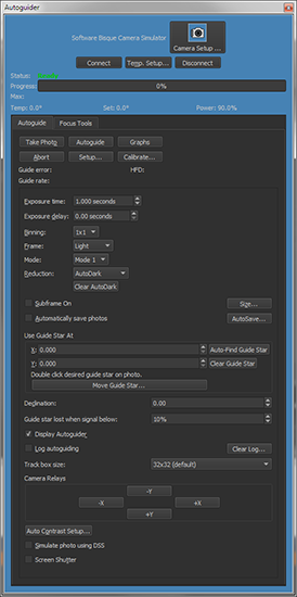
To calibrate the autoguider, from the Autoguider tab, click the Autoguide tab. For an overview of every control on the Autoguide tab, see “Autoguide Tab” on page 607.
Figure 286: The Autoguider window.
To autoguide, you need either a camera that will be dedicated to autoguiding, such as a video camera, SBIG ST-i, or an SBIG dual CCD camera that has its own built-in autoguiding detector. Consult the camera documentation for instructions on how to connect the autoguider cable to the camera. The other end of the autoguide cable attaches to your mount; consult your mount documentation for the location of the autoguider connection.
Not all mounts support input from an autoguider. Contact the mount manufacturer for information on how to build an interface box or cable to fit such a mount. Most cameras come with a standard autoguider cable. If the standard cable doesn't fit your mount (such as for a Takahashi mount, or a Vixen Sky Sensor-equipped mount), consult the mount documentation for information about building or buying a suitable cable. Some mounts require the use of third-party relay hardware to provide appropriate guide signals; read your camera and/or mount documentation for details.
When calibrating the autoguider, selecting an appropriate calibration star is important. As you will see shortly in the list of possible errors, the brightness and location of the star used for autoguider calibration plays a major role in the success or failure of the calibration. Here are some tips in picking a good autoguider calibration star.
· Don't use a dim, hardly recognizable, calibration star.
o The calibration star should be bright enough to show clearly against the background. Typically, this is achieved if you can visually and easily identify the star on the autoguider photo using the Cameras+ Module’s standard auto-contrast routines. In other words, do not try to calibrate the autoguider using a dim, hardly recognizable star. You can run the cursor over the star and the background to see how bright they are; the brightness values appear at the left of the status bar at the bottom left of the photo window. The longer the exposure, the brighter the stars and background, but star brightness will increase faster than background brightness. If you can't find a suitable calibration star for a given exposure, increase the exposure time to see if any good candidates emerge.
· Don't use a saturated calibration star.
o The calibration stars brightness should not be close to the camera’s saturation level. The calibration star brightness will indeed vary, and you want to make sure it does saturate because saturation can lead to an incorrect star position and an incorrect or invalid autoguider calibration.
· Don't use a calibration star close to the edge of the CCD.
o The calibration star should not be near any edge of the autoguider CCD. This is critical when calibrating, since the Cameras+ Module will move the mount during autoguider calibration, and you don't want the calibration star to move off the detector. If the calibration star moves within 10 pixels of an edge, calibration will fail with an error stating so. You can use the camera relay buttons, the telescope's motion controls, or the mount's hand controller to move the calibration star more toward the center of the photo.
· During autoguide calibration, the Cameras+ Module finds the autoguide calibration star after each calibration relay adjustment (that moves the mount) by scanning the photo for the brightest light source. Because the Cameras+ Module can autoguide with the camera at any orientation, the Cameras+ Module does not make any assumptions about which way the calibration star will move with respect to relay activations and instead relies on the convention that the brightest light source on the autoguider photo during autoguide calibration is the calibration star. It is critical that during autoguide calibration the calibration star is significantly brighter than all other stars on the image otherwise the Cameras+ Module might incorrectly choose a different calibration star of similar brightness on a subsequent photo.
· Sometimes an unintended bright star will enter the photo after relay activation and usually results in the calibration error "invalid motion". In this case, pick a different autoguide calibration star in a different area. No other star in the tracking detector’s image should be close to the brightness level of the calibration star when calibrating. Otherwise, the Cameras+ Module can get confused about which star is the calibration star. You can use the Cameras+ Module to visually inspect the area around your selected guide star. Check for a distance equal to the 1.5 times the width of the area covered by the autoguiding CCD detector at a minimum. See the section “Select a Guide Star,” in this chapter, which can help you select a guide star.
· Accurate focus is required to accurate autoguider calibration. See “Using @Focus2” on page 687 for a reliable, automated focus method.
· Make sure the camera is cooled to the desired temperature setpoint to minimize noise/hot pixels.
· Turn on AutoDarks so that calibration images do not have as much noise or hot pixels.
· Do not use a long calibration time. The shortest calibration time that results in a successful calibration without a “Motion too small” error is optimal. There is not a lot to gain by having an unnecessarily long calibration time and there are in fact disadvantages; the whole calibration takes longer and the chances of the calibration star moving off the photo increase.
|
|
If you find that calibration repeatedly to fails because the Cameras+ Module finds a different calibration star from photo to photo, use the a subframe to capture less of the photo and aid the Cameras+ Module in finding the same bright, calibration star in photo to photo.
In other words, the subframe applies during autoguide calibration and you can use that to your advantage (and perhaps avoid a say pesky hot pixel in a certain region of the CCD). Avoid making the subframe too small or the calibration might move the guide star off the photo. |
· The Cameras+ Module can autoguide with either a dim guide star that is only a few counts above the background, which can be challenging, or a guide star that is bright and easily recognizable to the eye, which is less challenging. Autoguiding will do fine if the guide star is, say, 1,000 or more counts brighter than the background (more if you are doing tricolor imaging, since color filters will reduce the star's brightness, and the brightness of the star will often vary with the filter used).
· If your image composition makes it impossible to put the guide star near the center for autoguiding, you can still get good results if the star is at least 10 pixels from an edge. However, you increase the risk of losing the guide star during downloads from the Imager. The Cameras+ Module will automatically reacquire the guide star after Imager download but cannot do this if the guide star has moved off the detector. The greater the periodic and random errors of your mount, or the poorer the polar alignment, the greater the chances of losing the guide star during Imager download.
· When autoguiding, a star of similar brightness should not be within the autoguider track box, or the Cameras+ Module may jump between the two stars during autoguiding.
Typical autoguide exposures range from 1 to 10 seconds. Shorter and longer exposures can be used but are not often necessary. Guide exposures shorter than 1-2 seconds can be affected by seeing. When the guide exposure is very short, the autoguiding often winds up measuring and correcting for fluctuations in the atmosphere rather than actual guide star movement that needs to be corrected. If the autoguide exposure time is too long, the guide star could move so much that corrections are not being made when they should be, resulting in an undesirable final image with elongated stars.
The Cameras+ Module automatically accounts for autoguiding at a declination different from where the autoguider was calibrated, provided TheSky Professional is controlling the mount during autoguider calibration and during autoguiding. If no mount is connected, you must manually enter the declination that the telescope is pointing to in the box labeled Declination. An accuracy of one-tenth degree is sufficient if you enter this value manually.
The image you take as a reference image should be long enough to clearly acquire a star suitable for guiding. If you are unsure, start with an exposure of 1 to 10 seconds. You can always adjust the exposure length as needed.
Click Take Photo on the Autoguide tab to acquire an autoguider photo. Figure 287 shows the result for the guide detector on an SBIG ST-2000 camera. The guide detector is much smaller than the imaging detector, so download times are short. By default, a dark frame is automatically taken and subtracted from the light frame (reduction is set to AutoDark).
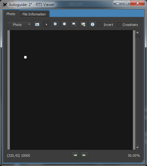
Figure 287: An autoguide image taken for reference. Note the isolated, bright star makes a good choice for a guide star.
Evaluate the image to determine if the exposure time provides a suitable brightness level for the guide star. As mentioned earlier, a good guide is at least 1,000 units over background level, and not near saturation.
You can either click Auto Find Guide Star on the Autoguide tab to have the Cameras+ Module pick the brightest star for the guide star, or you can double click any desired guide star on the photo. A white track box flashes briefly around the star to indicate that it has been selected as the guide star. Also, the coordinates of the selected guider star appear in the X and Y boxes of the Use Guide Star At control.
The Cameras+ Module can display the precise coverage of your CCD detector on the sky display (ST-237 and similar cameras) or both the imaging and tracking CCD detectors (ST-7/8/9/10) on the map of the sky. Figure 288 shows the projection for an ST-8E camera. The inner rectangle is the imaging detector; the small rectangle above it is the tracking detector. The circles show the position of the tracking detector if you rotate the camera. These circles can help you find an alternate guide star just by rotating the camera, instead of moving the mount. The Cameras+ Module does not require that the camera be orthogonal (square) to the mount to autoguide. It will calibrate and guide successfully at any camera angle.
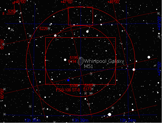
Figure 288: The imager and autoguider detectors of an ST-8E with an ST-237 guider camera.
To set up your camera's field of view indictor, follow these steps in TheSky Professional:
1. Click Display > Field of View Indicators.
2. Choose your telescope and detector and click Create My FOVIs.
3. Click the My FOVIs tab, turn on the checkbox next to your FOVI and click Center.
The field of view indicator will only appear when magnifications on the start chart are large enough to see it. Zoom in, if necessary, to see the field of view indicator (page 125).
In Figure 289, the pair of interacting galaxies known as Messier 51 (M51) is centered on the imaging detector, and celestial north is straight up on the Sky Chart. The box at the top shows that there are a few dim stars on the tracking detector, but none is very bright, and none are near the center. The two galaxies form a nearly vertical line with each other, and several dimmer galaxies are also in the frame. You could try to guide using the star at the eight o'clock position on the tracking detector, but for calibration you should move the mount to bring a brighter star onto the tracking detector.
A brighter guide star allows you to use a shorter guide exposure time. If your mount is very stable and accurate, you can use longer guide exposure times and therefore dimmer guide stars are suitable. If your mount has poor polar alignment, larger periodic error, or suffers from random movements during tracking, brighter guide stars are more important to a nicely autoguided Imager photo.
Figure 290 shows one approach to finding a nice, bright guide star: move the mount so that a bright star falls on the guide detector, while M51 remains in the same orientation. M51 has been moved away from the center of the imaging detector. If you want M51 near the center, you can also rotate the camera to bring a guide star onto the guide detector. If your mount has go-to features, you can control it from TheSky Professional. Changing the camera’s rotation requires a trip out to the telescope, unless the Cameras+ Module is connected to the rotator.
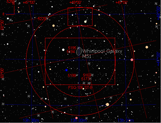
Figure 289: Placing a guide star on the autoguider.
If you were performing a calibration, the bright star in Figure 290 is clearly brighter than others in this field. It is an ideal star for calibration. For this star, use short exposure time; this also will speed up the calibration process. In general, you should expect to move your mount away from the object you intend to image to do a calibration, because putting a bright calibration star near the center of the detector is important to successful autoguider calibration. With the Cameras+ Module available to position the mount, you can move, calibrate, and return to your object very quickly.
If you want to keep M51 at or near the center for taking the actual image, rotating the camera to bring a guide star onto the tracking detector works well. Figure 290 shows that a rotation that puts north at about eight o'clock puts a reasonably bright star on the tracking CCD detector. You can experiment with TheSky Professional to find the right rotation angle, and then physically adjust the camera to the new orientation. Since the Cameras+ Module can guide accurately at any orientation, even 45 degrees away from orthogonal, you have complete flexibility in framing your images. If the Cameras+ Module is connected to a camera rotator, your FOVI can be linked to the rotator (page 723) so that when you rotate the FOVI on screen, the rotator hardware follows.
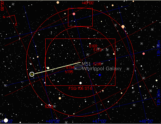
Figure 290: Rotating the view to look for a suitable guide star.
During calibration, the Cameras+ Module will move the mount for a period, then take another image and determine the motion of the calibration star (that is, how far the mount has moved). Each photo is displayed along with graphical arrows indicating how the calibration star moved so that you can follow along. These images and arrows (resultant calibration vectors) are a useful for diagnosing common problems that occurs during calibration.
The software measures the amount of movement of the calibration star from one photo to the next. The exact sequence is as follows:
1. Take an initial reference photo.
2. Active the +X relay, take a photo, measure calibration star movement.
3. Active the –X relay, take a photo, measure calibration star movement.
4. Active the +Y relay, take a photo, measure calibration star movement.
5. Active the –Y relay, take a photo, measure calibration star movement.
An ideal mount and imaging system concludes this sequence with the guide star in the exact same position as at the start of the calibration procedure. In most cases, there will be at least a small difference in starting and ending position due to whatever errors accumulated while the mount moved in all four possible directions.
It is intuitive to relate relay activation to calibration star motion when the camera is aligned square to the mount’s right ascension and declination axis. For example, when the camera is aligned square to the mount’s right ascension and declination axes, X relay activation corresponds to calibration star motion changing in X pixels on the resultant photo and Y relay activation corresponds to calibration star motion changing in Y pixels on the resultant photo. In contrast, if the camera is rotated so that it is not “square” with the right ascension and declination axis, activating, say, the X relay, will produce calibration star motion in both X and Y pixels on the resultant photo. The Cameras+ Module can cope with a completely non-square camera position. This gives a great deal of flexibility in selecting a guide star.
To set the time interval for calibration, as well as other related settings, click Setup on the Autoguide tab. See Figure 291 for the default appearance of the Autoguide Settings window. The calibration time is the length of time in seconds that each relay is activated during the autoguide calibration process.
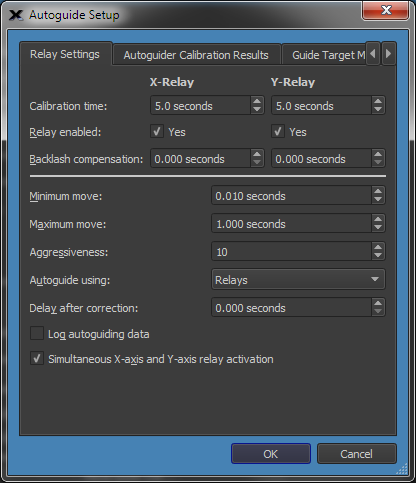
Figure 291: The Relay Settings tab on the Autoguide Setup window.
The calibration time you enter depends on, primarily, the focal length of your telescope, the pixel size of your camera and the bin mode. If the camera is reasonably well matched to the telescope (a camera with anywhere from 1 to 4 arcseconds per pixel), the values shown in the following table are useful starting values for calibration time.
|
Focal length (mm) |
Suggested calibration time (seconds) |
|
100-300 (typically a camera lens) |
15 |
|
300-500 |
10 |
|
500-1000 |
5 |
|
1000-2000 |
5 |
|
2000-3000 |
3 |
Here are the remaining autoguide setup parameters on the Relay Settings tab:
Determines whether autoguiding corrections are applied to the indicated axis. For example, if the mount’s polar alignment is exceptional and exposure duration is under about one hour, you can turn off corrections to the declination axis to avoid spurious corrections that result from atmospheric turbulence. In addition, if you are creating a tracking log to determine your mount’s periodic error, you will want to disable both axes.
Backlash exists when the motors on the mount must turn for some period after a change of direction before the gears fully engage and move the mount. Backlash compensation is the time that the Cameras+ Module should turn the motors to take up backlash when the direction reverses. Since guide speeds in right ascension are typically less than sidereal rate (0.5x is commonly used), no reversal occurs, and you should not set a backlash compensation time for right ascension backlash compensation unless you are using a mount autoguide speed of 1x sidereal or faster. You should always slightly under compensate for backlash; overcompensation leads to over correction and can make autoguiding impossible.
This specifies the minimum autoguiding correction that the Cameras+ Module will make. If the autoguide correction is less than this amount, no autoguiding correction occurs. When an autoguiding correction is equal to or greater than this amount, the autoguide correction will be made.
The longest time to move the mount during an autoguide correction. If you find that the mount is too active, no matter how you change other settings, this can force the Cameras+ Module to use shorter corrections. However, if possible, you should find the source of the problem and fix it instead.
A number from 1 to 10, indicating the relative aggressiveness of the corrections. With a setting of 10, the Cameras+ Module makes the full, computed correction. With a setting of 5, the Cameras+ Module makes fifty percent of the computed correction. With a setting of 1, ten percent of the indicated correction occurs.
If autoguider corrects cause the mount to overshoot, you can reduce the amount of the correction with this setting to minimize guiding errors. For example, when pointed near the zenith, your mount may be more responsive to corrections due to changes in balance. You can use a lower aggressiveness setting to compensate if your mount behaves in this manner.
This setting determines how the Cameras+ Module makes autoguiding corrections.
· Camera Relays: If a camera relay cable is connected directly to the mount (or connected through the SBIG relay box), then use the Camera Relays setting.
· RelayAPI (serial): If you are using a special, custom arrangement via the serial port of the computer running the Cameras+ Module, then choose RelayAPI (serial).
· Direct Guide™: Paramount Robotic Telescope Mounts, and mounts that employ the Bisque TCS support Direct Guide, a software technology that issues guiding corrections directly to the mount control system so that a separate autoguider relay cable is not required.
· PulseGuide: Similar to Direct Guide, ASCOM’s PulseGuide issues software-based autoguider corrections to the mount (Windows only, and where supported by the telescope driver) by changing the mount’s tracking rate.
If your mount tends to vibrate or bounce slightly after a correction is applied (needs a settling time), a delay can help ignore this oscillation. This is usually true only of lighter mounts, but it can also occur with larger mounts that overloaded.
When this checkbox is turned on, tracking data is saved to a log file.
· The name of the log file is automatically generated so that earlier tracking log data is never overwritten.
· The name of the log file has the form Auguider.001.log where .001 is incremented each time the Autoguide button is clicked.
· The location of the log file is defined by the AutoSave path. This option is immediately applied while autoguiding is in progress so that you can control when logging starts and stops. The Clear Log button on the Autoguide tab applies immediately as well. See the section “Graphically Examining Autoguider Data” on page 620 for information about the tracking log file.
Turn this option off if your mount is not capable of making an x and y correction at the same time (some older mounts). By default, this checkbox is on so that autoguider corrections that involve both an x-and y-relay activation is applied the mount at the same time. Some much older model Losmandy mounts (Gemini controlled mounts excluded) cannot perform simultaneous corrections.
Click OK to save changes. Click Calibrate to start the calibration process. You will see information reporting the progress of the calibration in the Autoguide tab, such as Moving Mount (Plus X). The calibration procedure starts with a new reference image and dark frame. It then moves plus and minus in the X and Y directions, measuring how the calibration start moves for each relay activation.
If there are any problems during the calibration, an error is reported in the calibration results windows. The following table lists common problems and explains what you can do to try to fix the problem.
|
Calibration Problem |
Solution |
|
Error message:
“Star too dim. Lost during +X, -X, +Y, or –Y” |
The guide star is too dim and could not be found on one or more of the photos acquired during calibration. Use a longer exposure or choose a brighter star. A star is too dim not just when it is too dim to be pulled from the background, but also when the brightest star in a calibration image is less than 25% as bright as in the preceding image.
|
|
Error message:
“Motion too small during +X, -X, +Y, or -Y move. Increase calibration time.”
|
The calibration time was too short to move the star far enough to get a valid result. The solution is to use a longer calibration time. For a valid calibration, the star must move at least 5 pixels. |
|
Error message:
“Star too close to edge after +X, -X, +Y, or -Y move.” |
The calibration star is too close to the edge of the image after a move. You can reduce the calibration time to cause less movement, and you can also begin calibration with the guide star at the center of the frame. This error will occur when the guide star moves to within 10 pixels of the edge.
|
|
Error message:
“Invalid motion in X- or Y-axis.” |
This error typically occurs when:
The brightest star in a calibration image is a star other than the original guide star due to random variations in brightness. The guide star should be significantly brighter than any other star in the image. A brighter star moves into the guide frame during calibration. The guide star should be isolated from similarly bright stars by at least 1.5 times the width or height of the guide frame in arcseconds. The mount is very inaccurate, with motion in X resulting in motion in Y, or vice versa. Check the Calibration Results graph to see if it provides any clues about what kind of invalid motion is contributed by the mount.
|
|
Error message:
“Unable to calibrate, both axes are disabled. At least one axis must be enabled to calibrate.”
|
With both axes disabled, no calibration is possible.
To enable one or both axes, from Autoguide tab, click Settings, then turn on the Enabled checkbox for one or both axes. |
|
Problem:
No calibration in one axis. |
If an axis is disabled, no calibration will occur for that axis.
To enable one or both axes, from Autoguide tab, click Settings, then turn on the Enabled checkbox for one or both axes.
|
|
Problem:
Calibration star moves out of frame. |
This problem can cause several different error messages to appear, depending on what happens when the calibration star moves off the photo. You might see “Star too dim” if another star winds up being interpreted as the calibration star, or you might see “Star too close to edge” or another message depending on where the brightest star winds up.
The Cameras+ Module displays the photos taken at each step in the calibration process; watch these images to see if the guide star is moving out of the frame. Use a shorter calibration time to keep the guide star in the frame and start with the guide star as close as possible to the center of the frame. Severe mount errors can also move the star out of the frame at longer focal lengths.
|
Once you have successfully calibrated the autoguider, you are ready to begin autoguiding. If you moved the mount to find a good calibration star, move it back to the object you want to capture.
Once your system is calibrated, you can start autoguiding. The Cameras+ Module supports autoguiding independent of imaging. This means that you can start an autoguiding session and then take a series of Imager images while the autoguiding continues uninterrupted. If the autoguider is integrated into the camera, as with an SBIG dual CCD’s, autoguiding is temporarily paused during the Imager photo download since the shutter must be closed during the Imager download and the autoguider shares the same shutter (and since the shutter is close the autoguider cannot capture photos).
If you have a good polar alignment – which is always a good idea when imaging anyway – the guide star will be more likely to remain within the autoguider track box when autoguiding resumes. If the guide star moves, the Cameras+ Module will perform corrections to move it back to the center of the autoguide window. If this move tends to be large, you can add a delay to your Imager exposures. This will give the Cameras+ Module time to make corrections before the next Imager exposure begins.
The larger the corrections, the longer the delay should be to give the autoguider time to settle down. For most applications, use a delay that is a few seconds longer than two times the autoguide exposure. For example, if your guide exposure is 4 seconds, then use a delay of about 10 seconds. The extra time allows for downloading the autoguider images and processing time. If you find that your mount requires shorter or longer delays, adjust accordingly.
Once you have calibrated the autoguider, you can begin autoguiding. A typical autoguiding session includes the following steps:
1. Adjust the position of the mount if necessary to put a suitable guide star on the autoguider detector.
2. Click Take Image on the Autoguide tab and verify the location of the guide star using an appropriate exposure length. If you are not sure, try 10 seconds.
3. If the brightness of the guide star is to too high or too low, adjust the exposure time. Aim for a brightness level of about 1000 counts and less than saturation.
4. Enter the current declination of the telescope. If you are using TheSky Professional to point your telescope, this will be filled in automatically when you click Autoguide.
5. Click Autoguide to begin guiding.
If you have TheSky Professional controlling your mount, it will automatically get the current declination of the telescope and use it to scale your calibration. If you move a large distance across the sky, or if you cross the meridian, then you may want to do another calibration. If you are imaging at longer focal lengths (2500 mm and larger), you can calibrate before every image if necessary to get the best possible autoguiding out of your system.
During autoguiding, the Cameras+ Module continuously updates the autoguider photo to show the guide star. The current autoguide error appears near the top of the Autoguide tab, showing the number of pixels that the guide star has moved from the original position (X Error and Y Error). These numbers may be positive or negative and are reported for both X and Y directions to the nearest hundredth of a pixel. Each photo captured for autoguiding shows a progress bar in the line for the autoguider at the Autoguider tab.
Autoguiding will continue until the Abort button is clicked. If there is an error during autoguiding, autoguiding will continue, when possible, for instance if the guide star’s brightness falls drastically due to clouds, autoguiding corrections are not made and autoguiding continues until the guide star brightness returns. If the guide star is lost and will not return (such as when the telescope is bumped), abort autoguiding and start over.
When using an SBIG dual CCD, the shutter will be closed when the Imager photo is being downloaded from the camera. Autoguiding is suspended while the shutter is closed and will resume after the Imager download is complete. If the mount’s polar alignment is good, the guide star will still be visible, and autoguiding will resume. You can enter an exposure delay in your Imager exposure(s) to allow for guiding corrections to settle right after the guide star is reacquired.
When should you recalibrate? The simplest way to tell is to start an autoguiding session and observe what happens. Start autoguiding after the telescope moves to a new position. Observe what happens to the X error and Y error numbers. If the both stay within +/- 1.0 pixel, you will likely have good results. If both stay within +/- 0.5 pixel, then the seeing is very good, and you should get excellent results. If one or both shows values greater than +/- 1.0, either the seeing is poor, or you may need to recalibrate for the new position. The need to recalibrate varies greatly from mount to mount, your image scale, and only experience will show you what works best for your mount.
Sometimes, autoguiding will not work as expected. Common problems, and possible solutions, include:
|
Autoguiding Problem |
Suggested Solution |
|
No corrections occur, and the X and/or Y Error numbers continue to increase |
Most likely, autoguiding corrections are not getting to the mount, check the cable between the camera and the mount. Make sure that corrections are enabled for the appropriate axes. Verify that the guide speed is set to an appropriate value (usually 0.5x sidereal) for the mount. You can test connections by pressing the relay buttons on the Autoguider tab and verifying if the stars in the photo move accordingly or worst case see if the mount’s coordinates change (warning you will have to press a relay button a long time before seeing a change in mount the position reported by the mount.
|
|
Corrections tend to oscillate between positive and negative values (for example, +1.3 and –0.9) |
If the load on your mount is too carefully balanced, the mount will be unusually sensitive to guide corrections, and may overshoot. You want a slight but definite excess of weight on the east side. This keeps the gears meshed and reduces the tendency of the mount to over-react to corrections. Oscillations can also occur when working near the zenith. You can also simply reduce the aggressiveness setting to see if that will eliminate the oscillation. Sometimes the mount will simply have a resonant period like the exposure duration and certain correction speeds; try a shorter or longer guide exposure length to see if it will eliminate the oscillation.
|
|
The mount suddenly makes large movements, and then comes back to zero. |
A “large movement” is any sudden movement of two pixels or more. This usually results from irregularities in the mount's bearings or gears, and may limit the success you will be able to achieve with autoguiding. Shorter exposures can help by allowing you to complete an image before you hit one of the large movements. Contact your manufacturer to see if you might need to replace a worn or damaged part. Dirt or grit in the gears can also cause this problem. Another possibility: wind gusts. If it's very windy, you may not be able to guide or track successfully, as the mount will bounce around. The larger and/or longer your telescope, the more likely it is to catch wind and cause deflections that will show up as guiding errors. In some cases, if the movements are not extreme, you may be able to guide successfully by shortening the guide exposure so that the Cameras+ Module can detect these movements sooner and correct for them more often. Guide exposures of 1-3 seconds can give you better results on less-expensive mounts, but not all objects will have a sufficiently bright guide star for you to try this option.
|
|
The guide star suddenly disappears |
The most common cause for this is simply clouds. Guide exposures are short enough that many stars will simply disappear if even a thin cloud moves through that part of the sky. If your mount is well aligned to the pole, and tracks accurately, you can sometimes simply wait out the cloud and guiding will resume when it passes. Any exposure you were taking during the time the cloud was in the way may or may not be salvageable. The guide star can also disappear if the mount is disturbed, in which case you probably have also lost your polar alignment. You might have touched your mount accidentally, but even a stray cat rubbing against a tripod leg has been known to cause trouble!
|
|
Corrections occur, but the X and Y errors are large and random |
This could be a sign of over correction. Try recalibrating and see if that happens smoothly. Another option is to lower aggressiveness setting. Try lowering the aggressiveness one unit at a time and see if you get any improvement. Stop lowering the aggressiveness when you get into the range of +/- 1.0 pixels (average seeing) to +/- 0.5 pixel (good seeing). Problems with your mount's bearings or gears are another potential source of trouble; consider tuning your mount if you get wild changes in the X and Y errors. For any given mount, there is a limit to how accurately it will track and autoguide; if tuning and/or service won't improve your results, you may need to upgrade your mount to work at a given focal length.
|
|
The guide star keeps trying to move in a specific direction. |
If the move is always in declination, this is most likely the result of a polar misalignment that is fairly large (more than 0.5 degree). If the autoguider is able to handle the movement in declination and keep it within a trouble-free range, the only concern is field rotation for long (one hour or more) photos or series of photos. If the autoguider fails to make the corrections and keep the error in a reasonable range, you can usually solve this problem by refining your polar alignment. See “Camera-Assisted Drift Alignment,” later in this chapter.
|
|
The guide star wanders slowly back and forth. |
Typically, this happens in right ascension, and you are seeing the periodic error of your mount. If your camera is oriented with north up, this will be a side-to-side (x pixels) motion in the autoguider photo. If the camera is turned 90 degrees (east or west up), then the motion will be up and down (y pixels). Periodic error usually results in slow, steady changes that go back and forth, so it is relatively easy for the autoguider to compensate. If your mount can record periodic error and then compensate for it (usually called PEC, for periodic error correction), you can use it or not, as you wish. It will not harm the performance of the autoguider if PEC and the autoguider are operating at the same time. However, the autoguiding is usually able to compensate for periodic error on its own, and you do not need to engage your PEC feature to get accurate guiding. You can also use the autoguider to log guide star motion which is sufficient to create PEC for capable mounts.
|
The table below lists the controls in the Autoguide tab.
|
Control |
Description |
|
Take Photo |
Click this button to take a photo using the current Exposure Time, Exposure Delay and other settings.
|
|
Autoguide |
Click this button to initiate autoguiding.
|
|
Graphs |
Click this button to display the Autoguiding Graphs window.
|
|
Abort |
Click this button to abort the camera operation in progress.
|
|
Setup |
Displays the Autoguide Setup window.
|
|
Calibrate
|
Start the autoguider calibration process. |
|
Exposure Time |
Enter the exposure time, in seconds, for the autoguider photo.
|
|
Exposure Delay |
Enter a pre-exposure delay in seconds.
|
|
Binning |
Enter the camera binning.
|
|
Frame |
The type of photo to be acquired: Light Dark Bias Flat
|
|
Reduction |
Choose the type of reduction that is applied to each image acquired. None AutoDark Full Calibration
|
|
Clear AutoDark |
Clears the AutoDark frame causing the Cameras+ Module to acquire a new dark frame on the next photo (when Reduction is set to AutoDark).
|
|
Sub-frame On |
When checked, only a portion of the CCD is acquired when a photo is taken.
The sub-frame size is set by either dragging a sub-frame on the photo or by typing in the size after clicking the Size button.
|
|
Size... |
Type in the size of the desired sub-frame.
|
|
Automatically Save Photos
|
When checked, every photo is automatically saved to the drive. |
|
AutoSave... |
Click to display the AutoSave setup window.
|
|
Use Guide Star At X, Y
|
The x and y pixel coordinate of the guide star. |
|
Auto-Find Guide Star
|
Scans the photo for the brightest guide star and sets Guide Star XY accordingly. |
|
Clear Guide Star |
Removes any selected guide and sets guide star’s X,Y position to 0,0.
|
|
Declination |
The telescope's declination.
|
|
Reverse X |
Allows reusing of autoguide calibration results after flipping a GEM even though initial calibration happened on the other side.
Note that the Cameras+ Module, when used with a TheSky Professional-controlled mounts, automatically reverses the X direction.
|
|
Display Autoguider |
This checkbox is on by default and forces every autoguider photo acquired to be displayed. On slower computers, turn this checkbox off so that autoguider photos are not displayed and increase the photo throughput.
|
|
Log Autoguiding |
Generate a tracking log for periodic error correction.
|
|
Clear Log... |
Delete the existing autoguider log file.
|
|
Track Box Size |
Choose the size of the track box, in pixels.
|
|
Camera Relays*
|
Click or click and hold one of the +X, +Y, –X, -Y buttons to activate the camera relays in that direction.
|
|
Auto Contrast Setup…
|
Click this button to show the Auto Contrast window and choose the desired method to adjust the contrast method to apply to subsequent photos.
Auto Contrast options:
· SBIG: Use Santa Barbara Instrument Group’s auto-contrast algorithm to compute the photo’s black and white points. · Bjorn: Use the proprietary algorithm, along with the selected Background and Highlight options to compute the photo’s white and black points.
|
|
Simulate Photo Using DSS |
Turn on the Simulate Photo Using DSS checkbox to take photos of Digitized Sky Survey objects, instead of collecting “actual” photons with the camera’s detector and a telescope.
|
|
Screen Shutter |
Turn this checkbox on to show a completely black computer during exposures. This can minimize “light leak” from your monitor.
|
|
* “Camera relays” is used as a generic term for the method of moving the telescope during autoguiding. See “Small Mount Adjustments via Camera Relays, Direct Guide, or PulseGuide” on page 583 for other means to adjust the position of the telescope while autoguiding. |
|
Once you have mastered enough CCD imaging skills to take focused photos, the next step is to lengthen your exposures so you can take deeper, more detailed, and cleaner photos of your favorite celestial objects. The accuracy of your mount determines how deep you can go. The more accurate your mount, the easier it will be to take long exposures.
Some mount manufacturers specify the accuracy of their mounts. This accuracy is expressed in arcseconds. An exceptional mount can guide with accuracy of 2-3 arcseconds or less. A very good mount can guide to about 5-6 arcseconds. The average low-cost mount guides to within 15-20 arcseconds. Mounts with even less accuracy are less suitable for CCD imaging unless the focal length of the telescope or lens is exceptionally short.
Whatever the accuracy of your mount, the key to success is matching the focal length of your telescope or camera lens to the abilities of the mount. For example, consider a CCD detector with pixels that are 9 microns square, such as the ST-7E. The angle on the sky covered by each pixel varies with the focal length of your telescope:
|
ST-7E (9-micron pixels) |
|
|
Focal Length of the Telescope (mm) |
Angle of Sky (arcseconds) |
|
300 |
6.2 |
|
500 |
3.7 |
|
700 |
2.6 |
|
900 |
2.1 |
|
1100 |
1.7 |
For example, imaging with a 300mm camera lens, at least 6 arcseconds of error are tolerable because a single pixel covers just over 6 arcseconds. Imaging with a refractor that has 1100mm focal length, a single pixel covers only 1.7 arcseconds, and the need for tracking accuracy is almost four times higher.
In practice, star images cover more than one pixel due to atmospheric scattering, the same process that causes stars to twinkle, so you would have more leeway than shown here. The important concept is that the shorter your focal length, the less the need for tracking accuracy in your mount.
A short focal length alone will not necessarily solve the problem, however. Smaller or larger pixels on your CCD detector alter the numbers. As shown in the following table, large pixels cover more sky for a given focal length, and smaller pixels cover less sky:
|
ST-9E (20-micron pixels) |
ST-237 (6.8-micron pixels) |
||
|
Focal Length of Telescope (mm) |
Angle of Sky (arcsecs) |
Focal Length of Telescope (mm) |
Angle of Sky (arcsecs) |
|
800 |
5.1 |
300 |
4.7 |
|
1000 |
4.1 |
500 |
2.8 |
|
1200 |
3.4 |
700 |
2.0 |
|
1500 |
2.7 |
900 |
1.5 |
|
2000 |
2.0 |
1100 |
1.3 |
For best results, match the focal length of your telescope to both your CCD camera and your mount. Most CCD imagers aim for a camera/telescope combination that yields from 1.5 to 4 arcseconds per pixel. Your choice of mount should match the capabilities of whatever combination you select. You can calculate the arcseconds per pixel of your camera/telescope combination using the following formula:
(<pixel size in microns> / <focal length in mm>) * 206
Experience shows that, to get good results, your mount error should be no more than +/- 2 pixels. For high-quality images, one and a half times the arcseconds per pixel value is a safer limit. Very high precision results demand a value of a single pixel. For very long focal lengths (2500mm and up), local seeing and other conditions becomes more important, and the calculations are not so straightforward; experience of local conditions is needed to assess the requirements for the mount.
In general, then, for high-quality images, a mount should be able to guide to within 2.25 and 6 arcseconds, depending on the pixel size of the CCD camera in relation to the focal length of the telescope.
|
|
If your mount is not providing the pointing accuracy needed by your telescope, you can either use a focal reducer to shorten the focal length of your telescope or take steps to increase the pointing accuracy of your mount, or both. |
If you already own a mount, and want to assess its approximate pointing accuracy, you can follow this procedure.
Mounts come in a variety of mechanical drive designs. Many mounts intended for use CCD cameras involve a worm and worm gear, as shown in Figure 292. There is normally one pair for right ascension, and another pair for declination, but some mounts are only driven in right ascension.
A motor drives the worm gear with a gear reduction system between the motor shaft and the shaft of the worm that offers increased torque and lower rotation speeds at the worm-gear interface. The worm drives the worm gear, which is attached to the shaft of one of the mount’s rotating axes. The right ascension shaft turns at sidereal rate, which is the rate stars appear to move across the sky (approximately one revolution per day). The motor speed and gear ratios are set to track accurately at the sidereal rate. Paramount mounts with TPoint and ProTrack™ additionally compensate for refraction, gear errors and even tube flexure to correct the sidereal rate to the actual tracking rate of the imaging system for the highest possible accuracy.
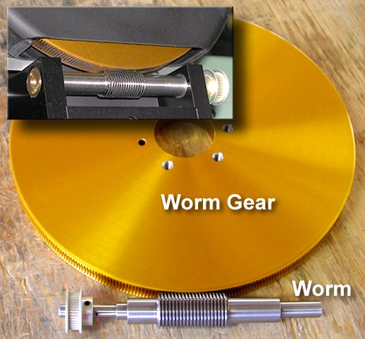
Figure 292: Example worm and worm gear.
To track and autoguide accurately, a worm-driven mount must often be adjusted or tuned in several ways. Before using a mount for autoguiding, we suggest the following; please consult your mount's documentation or the manufacturer for specific procedures on making these adjustments:
· Verify that the worm and worm gear are properly seated. If the end bearings of the worm are too tight, the worm will bind and could be damaged. If the worm is too loose between its end bearings (end play), reversals of direction will be erratic. Endplay in the worm gear is the usual cause if you observe that the mount initially and briefly moves in the wrong direction when reversing directions.
· Verify that the mesh between worm and worm gear is appropriate. Some mounts are made from harder materials and to closer tolerances, and these will typically require a very tight mesh between the worm and worm gear. Other mounts are made of softer metals, or to looser tolerances, and will require a looser mesh. If the mesh is too tight for the design, the gears will bind and could overheat or be damaged. If the mesh is too loose, there will be excessive backlash. Some mounts have built-in backlash compensation that allows you to keep the gears appropriately loose; the Cameras+ Module provides software backlash compensation that serves the same purpose. During backlash compensation, the motor is run at a higher speed to take up slack in the gears. Too much compensation will result in a jerky movement; too little compensation will result in a delay before a guiding correction is effective. It is always better to have too little rather than too much backlash compensation. If in doubt about how tight to mesh the gears, err on the side of being too loose. See the section “Assessing Mount Accuracy” on how to measure backlash.
· A slow-turning motor usually has less torque (that is, less force available to move the mount). This means that a slowly turning motor is more likely to stall than one that is turning quickly. If the worm and worm gear are too tightly meshed, the slowdown to 0.5x sidereal that occurs during autoguiding could cause the mount to stall or move at the wrong speed.
· Cold conditions can cause some lubricants to become stiff, and this can alter the behavior of your mount. If you need to operate your mount in very cold conditions, or if you observe increased stiffness in cold weather, check with the manufacturer to find out whether you will need to use different lubrication for cold conditions.
· Some mounts, after tuning and adjustment, will have a large enough residual error that it will limit the focal length telescope you can use successfully. The larger the error (from periodic and non-periodic sources), the shorter the focal length of the telescope you can use for imaging. The actual limit depends on the weight of your telescope and its overall physical length as well as its focal length. Long, heavy telescopes require more careful balancing and tuning for successful guiding. Focal reducers are available to help with this situation. Otherwise, you will need to use a telescope with a shorter focal length.
· Test the balance of your mount in various positions. Off-center equipment, such as a finder offset from the centerline of your telescope, or a camera attached piggyback fashion onto your telescope, can dynamically alter the balance of your mount as you point at different areas of the sky. A mount should always be loaded so that there is slightly more weight on the east side of the mount. This keeps the right ascension axis always loaded, eliminating backlash as a factor in right ascension autoguiding (as long as the correction speed is less than sidereal rate). If off-center equipment does cause the balance to change at different pointing angles, you can either rearrange equipment and/or counterweights after pointing to a new area of the sky, or you can incorporate sliding weights or some other weight-shifting system into the design of your setup. An out of balance mount can oscillate or wander unpredictably or require a new calibration when pointing to different parts of the sky even if the declination remains similar.
· You can calibrate your setup at a higher correction speed than you use when autoguiding. This tends to mask some errors, but it is not a cure-all. It slows down the correction process, and if your mount tends to be over-responsive, it can eliminate unnecessary corrections and provide smoother autoguiding.
More than any other single factor, the ability of your mount to track accurately and to respond quickly and smoothly to guiding corrections determines the success of your imaging. It is well worth measuring the accuracy of your mount and tuning and adjusting it to improve that accuracy to the greatest degree possible.
To track accurately, your mount needs to be aligned close to the celestial pole. Many mounts include a polar telescope (also called a bore telescope or bore sight) to help you polar align. There are many kinds of polar telescopes, but most contain a reticle that allows you to point the mount at specific stars to achieve alignment. Most mounts also contain provisions for aligning in either the northern or southern hemispheres.
Although you do not need perfect polar alignment for autoguiding, there are some issues to be aware of with respect to polar alignment. If you are taking single images of less than five minutes, even a rough polar alignment will be satisfactory if you are autoguiding. The lack of a perfect alignment will cause the field of view to drift during the exposure, but the autoguider will detect the drift and correct for it. The field will rotate a small amount during the exposure, but if the exposure is short enough, the amount of rotation is generally negligible. If you are concerned about the effects of field rotation in your photos and use TPoint, type FROT in the Command text box on the Command Line tab of the TPoint Module window to show the amount for field rotation, in radians per hour, over a range of declinations.
Autoguiding can correct for small misalignments to the celestial pole. If the misalignment is too large, however, the autoguider will have to make large, frequent corrections making the autoguider work very hard and only high-quality mounts will respond accordingly. The larger the misalignment, the shorter your guide exposures must be to make corrections before they become too significant and pollute the Imager photo (stars not round).
If your exposures are longer than fifteen minutes or so, rotation of the field over time may become an issue. If you are combining short-duration images for better signal-to-noise ratio or for color, the routine must also rotate the photos before combining.
Very short focal lengths are more sensitive to field rotation because the image covers a larger area of the sky. You can minimize field rotation by taking the time to polar align your mount very carefully. Use the polar telescope for rough alignment, and then use drift alignment to refine alignment. You can do drift alignment manually, or you can use the CCD camera to assist. You can also use the TPoint Module, a Software Bisque software tool that increases telescope-pointing accuracy, to achieve extremely accurate polar alignment.
1. Level the base of the mount if possible. A level mount is not required, but it makes adjust easier by reducing interplay between altitude and azimuth adjustments.
2. Locate a bright star near the celestial equator and near the meridian (the midpoint between east and west). Center the star in the crosshairs of an illuminated reticle eyepiece.
3. Observe the star until it drifts north or south; ignore drift to the east or west. If the star drifts north, adjust azimuth so the mount points more to the east. If the star drifts south, adjust azimuth so the mount points more to the west. Repeat until north/south drift becomes negligible over a 5-minute observing period.
4. Locate a bright star near the celestial equator and near either the east or west horizon. Center it in the crosshairs of an illuminated reticle eyepiece.
5. Observe the star until it drifts north or south; ignore drift to the east or west.
If you are looking east:
· If and the star drifts north, adjust altitude downward.
· If the star drifts south, adjust altitude upward.
If you are looking west:
· If and the star drifts north, adjust altitude upward.
· If the star drifts south, adjust altitude downward.
Repeat until north/south drift becomes negligible over a 5-minute observing period.
|
|
To determine which way is north in the eyepiece, move the telescope toward the south and note the direction the stars move; they are moving toward the north in the field of view.
In general,
· If you move the telescope to a slightly more positive declination the stars will move south in the field of view. · If you move the telescope to a slightly bigger right ascension the stars will move west in the field of view. |
Calibrate your autoguider as described earlier in this chapter.
1. See if the camera is currently orthogonal (square) to the mount. If you have performed a calibration, you can use the Cameras+ Module to tell you how close the camera is to orthogonal. On the Autoguide tab for the Autoguider, click Setup. This opens the Autoguide Setup window. Click the Relay Calibration Results tab. This displays a graph showing how the camera is oriented with respect to the right ascension and declination axes of the mount. Ideally, the X- and Y- relay vectors will line up closely with the X- and Y-axis of the photo/CCD (Figure 293). Ideally, but not necessarily, the angle of the +X vector should be close to zero, and the +Y axis vector should be nearly perpendicular to the +X vector. If your camera is rotated with respect to the mount axes (Figure 294), you will not get accurate readings for camera-assisted drift alignment.
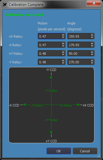
Figure 293: Relay calibration results that show the camera is ready to assist with drift alignment.
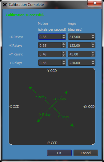
Figure 294: The camera axes are not square to the mount axes. The camera rotation is not well situated for assisting with drift alignment.
2. If the camera isn't square with the mount, adjust the camera so that the top of the CCD detector points toward north. For the greatest accuracy, repeat calibration to verify alignment of the camera. Repeat until you've got everything lined up to your satisfaction.
3. Using the Autoguide tab, set an appropriate exposure time (for example, 5-10 seconds), and then click Take Photo. Check your results and adjust the exposure time as needed. Double click on a suitable guide star.
4. Click Log Autoguiding. This allows you to examine your data later if you have any questions about the progress you are making toward polar alignment. The log file is named autoguider.XXX.log and can be found under the camera's autosave folder. See the next section, “Autoguider and Tracking Log,” for a list of the fields contained in the log file.
5. To measure drift, you need to turn off corrections. From the Relay Settings tab, uncheck the Relay Enabled checkboxes for X-and Y-relay. Note: Remember to re-enable corrections when you are done.
6. Click OK to close the Autoguide setup window.
7. Click the Autoguide button on the Autoguide tab. You can now observe the Y (declination) error to measure drift very accurately and very quickly. You can examine the log file at any time to determine the total amount of drift versus elapsed time. Positive Y error values are northward drift; negative Y error values indicate a drift to the south.
8. Once you have a measurement of the current amount of drift north (+Y) or south (-Y), adjust the mount as for manual drift alignment and repeat the autoguiding process.
9. For optimal results, continue drift aligning until you can autoguide for several minutes with a Y error no larger than +/- 1.0. For critical applications, continue until you can autoguide for five minutes with a Y error no larger than +/- 0.5.
You can turn on logging of autoguider operation using the either the Log Autoguiding Data checkbox on the Autoguide tab or the same checkbox under the Setup button on the Autoguider tab. Turn the checkbox on to collect autoguiding data. New autoguiding data is always automatically saved to a new file per autoguiding session. To clear the log file, click the Clear Log button.
A sample autoguider.log file is shown below. The lines are wrapped because the data content is too long to fit on a single line here. In the file itself, each line of data is a single line.
TheSkyX Cameras+ Module Autoguiding Log
Camera = Imager's built-in autoguider
X Axis = Enabled
Y Axis = Enabled
ExposureTime = 0.10
Aggressiveness Factor = 10
Calibration Time X = 4.00
Calibration Time Y = 4.00
Calibration declination = 0.00
Declination now = 0.00
Minimum Move = 0.01
Maximum Move = 1.00
Backlash X = 0.00
Backlash Y = 0.00
Delay After Move = 0.00
Autoguide using Relays
Calibration Determined Velocity Vectors (pixels/sec)
XPlus Speed= 5.00106 (XPlus X= 5.00076, XPlus Y= 0.05490) Angle= 0.00000
XMinus Speed= 5.00016 (XMinus X= -4.99985, XMinus Y= -0.05594) Angle= 0.00000
YPlus Speed= 4.99963 (YPlus X= -0.00182, YPlus Y= -4.99963) Angle= 0.00000
YMinus Speed= 4.81357 (YMinus X= 0.05687, YMinus Y= 4.81323) Angle= 0.00000
|Elapsed Secs|RefCentroidX|RefCentroidY|CurCentroidX|CurCentroidY|GuideErrX |GuideErrY |TotGuideErr |XPlusRelay |XMinusRelay |YPlusRelay |YMinusRelay |PECIndex RA |PECIndex Dec|
| 0.0000| 49.8300| 49.0000| 49.7707| 48.9768| -0.0593| -0.0232| 0.0637| 1| 0| 0| 0| 0| 0|
| 2.4020| 49.8300| 49.0000| 49.8054| 48.9818| -0.0246| -0.0182| 0.0306| 0| 0| 0| 0| 0| 0|
| 3.3230| 49.8300| 49.0000| 49.8077| 48.9778| -0.0223| -0.0222| 0.0314| 0| 0| 0| 0| 0| 0|
| 4.2590| 49.8300| 49.0000| 49.8038| 48.9827| -0.0262| -0.0173| 0.0314| 1| 0| 0| 0| 0| 0|
| 5.1950| 49.8300| 49.0000| 49.9322| 48.3956| 0.1022| -0.6044| 0.6130| 0| 2| 0| 13| 0| 0|
| 6.1310| 49.8300| 49.0000| 49.8545| 48.8989| 0.0245| -0.1011| 0.1040| 0| 0| 0| 2| 0| 0|
| 7.0670| 49.8300| 49.0000| 49.8569| 48.9807| 0.0269| -0.0193| 0.0331| 0| 1| 0| 0| 0| 0|
| 7.9870| 49.8300| 49.0000| 49.8139| 48.9820| -0.0161| -0.0180| 0.0241| 0| 0| 0| 0| 0| 0|
| 8.9080| 49.8300| 49.0000| 49.8128| 48.9798| -0.0172| -0.0202| 0.0265| 0| 0| 0| 0| 0| 0|
0.0000| 0| 0| 0| 0|
The top portion of the file record the camera used, as well as which axes are enabled. The exposure time and the aggressiveness setting are also recorded.
The next section lists the calibration details. This is a text version of the information you see in the Relay Calibration Results window (Figure 293).
The bottom section contains a record of all guiding corrections. The example above shows only a few lines. You could have hundreds of correction entries for a long exposure. The following data is included for each correction; for X/Y coordinates, the origin is the upper left corner of the detector:
Heading |
Description |
|
Elapsed Secs |
Total number of seconds that have elapsed since the start of the current autoguiding session. |
|
RefCentroidX |
The X coordinate of the starting position of the guide star centroid. |
|
RefCentroidY |
The Y coordinate of the starting position of the guide star centroid. |
|
CurCentroidX |
The current X coordinate of the guide star, in pixels. |
|
CurCentroidY |
The current Y coordinate of the guide star, in pixels. |
|
GuideErrX |
The number of pixels the guide star has moved from the starting position along the X-axis. Equal to |
|
GuideErrY |
The number of pixels the guide star has moved from the starting position along the Y-axis. Equal to |
|
TotGuideErr |
The total current guide error in pixels, measured in a straight line from the origin. Equal to |
|
XplusRelay |
Time in one-hundredths seconds that the X-plus relay was on to make the correction. |
|
XminusRelay |
Time in one-hundredths seconds that the X-minus relay was on to make the correction. |
|
YplusRelay |
Time in one-hundredths seconds that the Y-plus relay was on to make the correction. |
|
YminusRelay |
Time in one-hundredths seconds that the Y-minus relay was on to make the correction. |
Heads up, the deciphering the autoguiding log is not intuitive when the camera is rotated with respect to right ascension and declination since an x pixel error may manifest itself to both an X and Y relay adjustment. Another potential point of confusion: resultant autoguiding corrections account for autoguiding at a declination different from the declination at calibration time so they may be bigger or smaller than what you might expect at first glance.
If you logged autoguiding information, you can open the log file from the Autoguiding Graphs window to see the data graphically. Press the Graphs button on the Autoguiding sub tab and from the Autoguiding Graphs window, right click the "X Pix Error" graph (or the "Y Pix Error" or "XY Err Pix" graph) and choose Open Autoguiding Log.
|
|
If you turn off corrections during autoguiding, in addition to errors caused by atmospheric seeing, the log file will contain a record of the periodic error of your mount. Let autoguiding proceed for one full revolution of the right ascension worm. This is usually in the range of four to seven minutes. Consult your mount documentation if you aren't sure or contact the mount manufacturer. To turn off corrections, click Setup on the Autoguide tab. Turn off the Relay Enabled checkboxes to disable the X- and Y relays. |
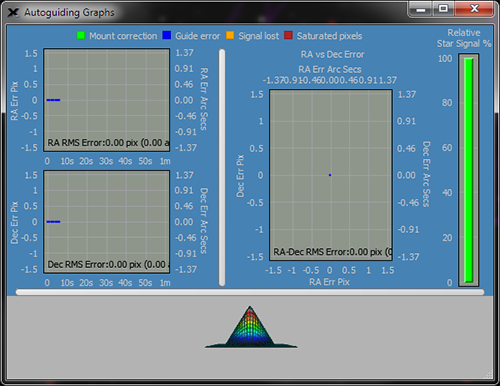
Figure 295: Sample autoguider graphs.
While autoguiding, press the Graphs button to display the Autoguiding Graphs window. These graphs give great visual feedback and provide insight into autoguiding performance at a glance.
The graphs show the X error in pixels and arcseconds (see note below), the Y error in pixels and arcseconds (see note below), the XY error as a scatter graph, the guide star’s relative signal as well as a three-dimensional graph of the guide star.
|
|
The autoguider’s image scale is computed from the Telescope Parameters on Imaging System Setup window (page 560). Make sure to highlight Autoguider’s Camera (not the Imager’s Camera) to view them.
If these values are not set, the autoguider graphs show errors in pixels, only.
|
The XY error graphs show the error for the last 100 autoguiding cycles. You can zoom in/out on the XY error graphs by holding your mouse over the graph and using the mouse wheel. Click and drag the graphs to scroll left or right. The graphs window is also sizable allowing it to be viewed “full screen” on a second monitor, for example.
Each point on the autoguiding graphs is color coded, as described in the table below.
|
Color of Point on Graph |
Description |
|
|
Blue points show the Guide Error, that is, distance the centroid of guide star moved in the photo. Guide errors can be caused by a host of factors, including poor mount tracking, polar drift, seeing errors and more.
|
|
|
Green points show the Mount Correction which is the angular distance the mount’s position was changed or corrected. The correction distance is computed based on on the star’s centroid (Guide Error), as well as the Aggressiveness, Minimum and Maximum Move parameters.
|
|
|
Orange points indicates Signal Lost which means the guide star’s signal (ADU) fell below a minimum threshold during a particular guiding sequence. Passing clouds are common cause.
|
|
|
Red points show that the guide star contains Saturated Pixels, meaning that the signal from the star for the given exposure time exceeds the maximum signal the camera can record.
Saturated pixels in a guide star make centroid determination, and therefore guiding, less accurate. Try using a fainter guide star, or a shorter exposure to mitigate pixel saturation.
|
Guide errors (the relative motion of the star computed from its centroid in each exposure)
You can change the viewing angle of the three-dimensional guide star by clicking and dragging within this window. Right click and choose properties to change the appearance of the three-dimensional star (these settings are not saved, and the three-dimensional star will return to its default settings on exit and restart).