
TheSky Professional with the Cameras+ Module and the TPoint module allow pointing samples to be acquired without human intervention through a process called automated pointing calibration. Once the Cameras+ Module has been configured to acquire CCD photos and your telescope and CCD camera’s field of view parameters have been determined, the TPoint module can be used to generate a distribution of optimal azimuth and altitude targets that are used to point the telescope.
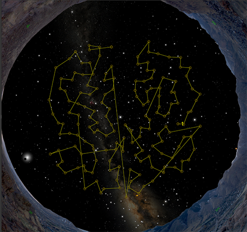
Figure 240: The yellow circles on the Sky Chart represent each azimuth and altitude target. The yellow line shows the path of the telescope.
During an automated calibration, at each target, a digital photo is acquired. Next, astrometric solution (sometimes referred to as a plate solve) using Image Link (page 322) is computed from the photo by comparing the positions of the stars in the photo with cataloged stars (Gaia, Hipparcos-Tycho, etc.). The difference in the telescope’s position and the coordinates computed from the astrometric center of the photo is recorded as a pointing sample (page 476).
This process is repeated for each target in the pointing calibration list.
Before getting started, make sure your imaging system meets the following minimum requirements.
· TheSky Professional. See “Controlling a Camera” on page 558 for details about setting up and using your camera. Note that TheSky Serious Astronomer does not provide a mechanism to take photos, so automated calibration is not supported.
· A “go to” or robotic telescope mount that is can be controlled by TheSky Professional.
You also need to determine the image scale, in arcseconds per pixel, of your imaging system, as well as the position angle of the CCD camera after it has been mounted to your optical tube assembly. See the Image Link documentation TheSky Professional and Serious Astronomer User Guide for details how. Or click the Take And Image Link Photo button on the Automated Pointing Calibration Run window to do this step for you.
Once you have configured TheSky Professional to acquire CCD images and quantified your imaging system, you are ready to perform an automatic pointing calibration run.
The Create Pointing Targets tab on the Automated Pointing Calibration Run window allows you to create, save and restore sets of pointing targets that can be used to acquire pointing samples during an automated pointing calibration run.
The circular blue region on this tab represents the visible portion of the celestial sphere from your location; the cardinal directions labeled for reference.
1 This line shows the current Custom Drawn horizon that can be defined on the Horizon tab of the Horizon & Atmosphere window (Display menu).
2 Click and drag this circle to define the starting altitude, or Azimuth Start for the pointing targets.
3 Click and drag this circle to define the ending altitude, or Azimuth End for the pointing targets.
4 Click and drag this circle to define the lowest altitude, or Altitude Start for the pointing targets. Note that no pointing samples are created below the custom horizon when one is present.
5 Click and drag this circle to define the highest altitude, or Altitude End for the pointing targets.
6 When connected to a telescope, the current position of the telescope’s crosshair is displayed.
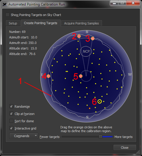
Figure 241: The Create Pointing Targets tab.
The upper left the Create Pointing Targets tab shows the number of points and the region of the sky that contains points when the Interactive Grid checkbox is turned on.
The right side of this tab shows a horizon to zenith map that contains a number of helpful items:
· The four cardinal directions appear near the edge of the map.
· The text NCP (or SCP in the southern hemisphere) shows the position of the celestial pole based on TheSky’s current location. The gray circle around this text represents 80 degrees declination.
· When the Interactive Grid checkbox is turned on, four orange circles appear on the map that can be used to define the regions of the sky that do not contain pointing samples. Click and drag each circle to define the start and end of the region in azimuth and altitude that contains pointing samples. No pointing samples are generated in areas outside this region.
· The yellow dots on the map are automatically generated pointing targets. Turn on the Interactive Grid checkbox and use the Pointing Target Separation slider to show fewer or more pointing targets.
· When the Clip Horizon checkbox is turned on, pointing targets below the custom drawn horizon are removed. See the “Horizon & Atmosphere Options” documentation in TheSky Professional and Serious Astronomer Edition User Guide for details about drawing custom horizon lines.
· The yellow dots with red circles are user-defined pointing calibration targets. Click anywhere on the map to add a target at that position (right-click the point to remove it). Each user-defined pointing calibration target added to the map is placed at the beginning of queue. In this way, you easily add and collect pointing samples near the telescope’s current position so that, after six “nearby” pointing samples have been collected, TPoint will significantly improve the telescope’s pointing accuracy on subsequent slews, making data collection much less error prone.
· When TheSky is connected to a telescope, the yellow telescope crosshair represents the current position of the telescope.
The current number of pointing targets defined on the map.
When the Interactive Grid checkbox is turned on, this shows the starting azimuth of the region that contains pointing targets. Otherwise, this text is hidden. Click and drag the appropriate orange circle on the map to adjust this value.
When the Interactive Grid checkbox is turned on, this shows the ending azimuth of the region that contains pointing targets. Otherwise, this text is hidden. Click and drag the appropriate orange circle on the map to adjust this value.
When the Interactive Grid checkbox is turned on, this shows the starting altitude of the region that contains pointing targets. Otherwise, this text is hidden. Click and drag the appropriate orange circle on the map to adjust this value.
When the Interactive Grid checkbox is turned on, this shows the ending altitude of the region that contains pointing targets. Otherwise, this text is hidden. Click and drag the appropriate orange circle on the map to adjust this value.
Turn on this checkbox to define random positions for the targets. When samples are too evenly spaced (not randomized), the TPoint model can potentially miss pointing errors.
Turn on this checkbox to exclude targets that fall below TheSky’s local horizon.
Use this scroll bar change the distance between pointing calibration targets. The smaller the distance between pointing targets, the more targets.
The commands pop-up menu contains commands to open, save or export calibration points, and quickly generate user-defined pointing calibration targets.
Click this command to open a Pointing Target File (simply a space delimited, properly formatted text file) that contains a list of pointing calibration targets.
A sample Pointing Target File is below:
GRID: 1 155.62550 16.19201
GRID: 2 148.04368 15.63469
GRID: 3 133.07751 15.84730
GRID: 4 123.59620 15.30152
GRID: 5 109.22322 15.45653
…
GRID: 258 291.95877 71.02200
GRID: 259 269.86198 69.62564
GRID: 260 244.91223 70.50135
GRID: 261 223.29501 71.79654
GRID: 262 199.52605 69.77031
Click this command to save a Pointing Target File. By default, these files are saved to the AutoCalibration folder in TheSky’s Application Support Files folder (page 28).
Click this command to update the Sky Chart to reflect the current pointing calibration settings.
Click this button to copy the list of targets to the Clipboard. This data can be used to write your own pointing calibration target scripts.
Click this command to remove all user-defined pointing calibration targets from the map. Individual points can be removed by right clicking the mouse over them on the map.
Click this command to add six user-defined pointing calibration targets near the telescope’s current position. Collecting six points “near” the telescope minimizes the initial slew distances to make data collection easier while TPoint is yet not available to improve pointing.
Click this command to add six user-defined calibration points that ensure a proper recalibration. See “Important Recalibration Pointing Sample Notes” on page 506 for more information about how to achieve optimal recalibration.
Once your imaging system has been setup and tested, performing an automated calibration is relatively straightforward.
1. Click the Automated Calibration button on the Calibration Run tab of the TPoint Module window.
2. Click the Setup tab.
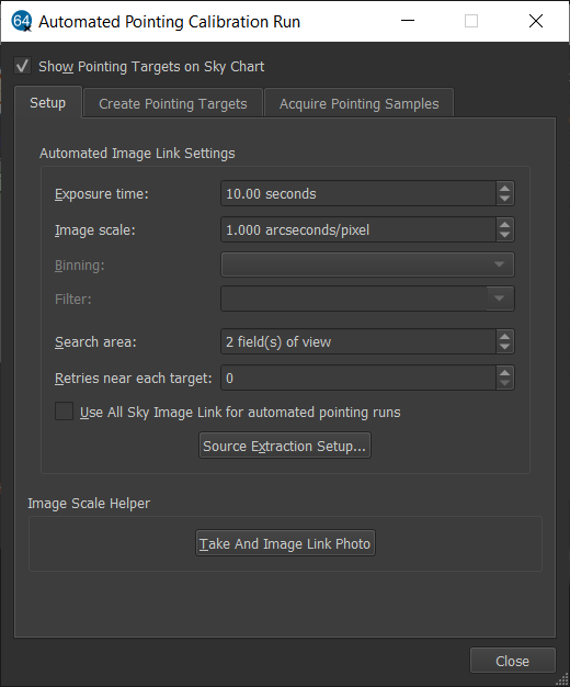
Figure 242: Setup tab on the Automated Pointing Calibration Run window.
3. Enter the Exposure Time, in seconds, that is used to acquire photos at each pointing sample position. You may have to experiment with your imaging system to determine optimal exposure times. For a cooled CCD camera on a typical-sized optical tube assembly, about 1-2 seconds is normally sufficient. The exposure time needs to be long enough to acquire at least six stars in the photo and short enough to avoid saturation and star “blooming.”
4. Enter the Image Scale, in arcseconds per pixel, for the optical system. If necessary, click the Take and Image Link Photo button at the bottom of this window to determine the image scale.
5. Enter the camera Binning option. 2x2 is recommended, especially for large format cameras and DSLRs. Binning effectively increases the sensitivity so that shorter exposure times can be used, and reduces download times, which speeds the entire acquisition process. Any perceived loss in resolution does not affect the pointing results.
6. Enter the Filter to use during the run. Non-clear filters will usually increase the exposure time required.
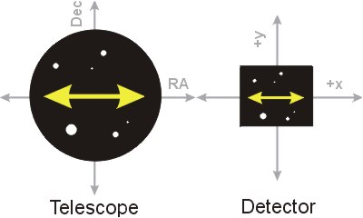
Figure 243: Recommended orientation for the CCD detector with respect to the telescope’s field of view
Figure 243 shows, rotating the camera on the optical tube so that +X and +Y on the CCD photo coincides with RA and Dec, respectively, can be helpful, but is not required.
7. Enter the Search Area, in fields of view, to scan when attempting to overlay the photo on the Sky Chart. Searching a larger area can help minimize the number of failed matches but may take longer to complete the calibration run.
8. Enter a number for the Retries Near Each Target. If no astrometric solution for the photo can be found, the telescope is slewed a small amount, and another attempt is made.
9. Turn on the Use All Sky Image Link for Automated Pointing Runs checkbox to use All Sky Image Link instead of the standard Image Link to find astrometric solutions. This can be helpful when the telescope has not been polar aligned, and slews are not yet accurate.
10. If necessary, click the Source Extraction Setup button to configure these parameters. See TheSky Professional and Serious Astronomer User Guide for details about the source extraction setup parameters.
11. If you do not know your imaging system’s image scale, click the Take and Image Link Photo button to have TheSky determine it for you.
· You may wish to enter a delay between exposures in the Exposure Delay text box on the Camera window to allow the telescope to settle.
The next step is to create the azimuth and altitude targets to point the telescope during the calibration process.
1. Click the Create Pointing Targets tab.
2. The blue region on this window represents an all-sky Sky Chart with small yellow circles at each target. The four orange circles can be used to define where in the sky the targets are created. Individually click and drag each to define the region of the sky where the targets appear. The upper two circles adjust the starting and ending azimuth. The lower two circles adjust the starting and ending altitude for the targets.
Clicking the Update Sky Chart button shows the new targets on the Sky Chart.
Once your imaging system has been characterized, and the targets to point the telescope have been defined, the automated calibration process can be started.
1. Click the Acquire Pointing Samples tab.
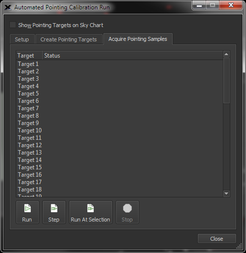
Figure 244: The Acquire Pointing Samples window.
2. Click the Run button to begin the automated process of acquiring pointing samples at each target.
When a pointing target is selected, its number appears next to the target’s circle on the Sky Chart.
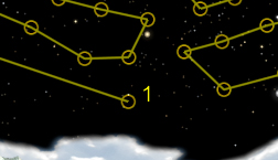
Figure 245: Sample Sky Chart when Target 1 is selected.
Click this button to start acquiring the pointing samples for each target in the list.
Click this button to acquire the pointing sample for the selected target only.
Click this button to start the script at the selected target, then all subsequent targets.
Click this button to stop acquiring pointing samples.
|
|
TPoint needs at least six calibration points before the telescope’s pointing accuracy improves. As calibration points are collected during an automated pointing calibration run, you can periodically run a Super Model (page 485) to improve the pointing model as you go. |
