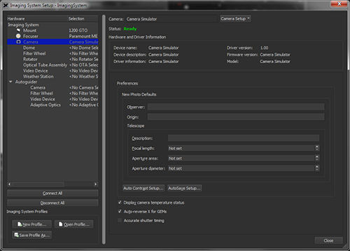
Once the camera and the computer are powered up, start TheSky Professional and then choose the Telescope Setup command from the Telescope menu. This displays the Imaging System Setup window. In the Hardware List on the left side of this window, click on the Camera text to display the camera setup options shown in Figure 276.
Click the Choose command from the Camera Setup pop-up to select your camera from list (see Figure 278) and click OK.
If you have a filter wheel, focuser or rotator installed/attached to the camera, select the model from the hardware list.
Figure 276: The Camera Setup options on the Imaging System Setup window.
Selecting Camera in the Hardware list displays camera driver details and other camera-specific preferences.
The Camera text at the top of the Imaging System Setup window shows the manufacturer and model of the currently selected camera.
The Camera Setup pop-up menu provides commands for choosing, setting up, connecting, disconnecting, and entering the Cameras+ Module serial number.
Click this command to display the Choose Camera window. The Camera list shows all supported models.
Click this command to display camera-specific port setup and driver options.
Choose this command to establish a connection to the camera.
Choose this command to stop communicating with the camera.
Choose this command to enter your Cameras+ module serial number. See “Activating the Cameras+ ” on page 552.
After selecting your model camera, click the Settings command in the Camera Setup pop-up menu to configure the communication interface and other camera-specific options.
This text box displays the current camera status.
When Camera is highlighted in the Hardware list on the Imaging System Setup window, the following camera hardware and camera driver-specific information is displayed.
This text box shows the name of the selected device.
This text box shows an abbreviated description of the device.
This text box shows additional information about the driver for this device.
This text box shows the version of the software driver used to control this device.
This text box shows the version of the device’s firmware, when available.
This text box shows the hardware’s model as reported by the device’s firmware, when available.
You can specify the default values that the Cameras+ Module will use when saving photos under the Preferences section of the Imaging System Setup window.
These values will be stored to the appropriate FITS keyword in the FITS header when new photos are acquired.
Enter the name of the observer. The value is saved to the OBSNAME FITS keyword in the FITS header.
Enter the place of origin of the photograph, typically the observatory name of observing site. This value is saved to the ORIGIN FITS keyword in the FITS header.
Enter the physical characteristics of the telescope or optical tube assembly below.
Enter a description of the telescope.
Enter the focal length of the telescope, in millimeters. This value is:
· Used to compute the AO Wander metric for the autoguider camera. When entering the telescope’s focal length for AO Wander, be sure to set the autoguider’s preferences by highlighting the camera listed under Autoguider, not the camera listed under Imaging System.
· Used to compute the image scale of a photo (in arcseconds per pixel) taken with the selected camera or autoguider. This image scale is displayed on the right side of the y-axis of autoguider graphs (see Figure 295).
· Saved as the value of the FOCALLEN keyword in the FITS header.
Enter the area of the telescope’s mirror, in square millimeters. The Aperture Area value is used to specify the area of the aperture, minus any central obstruction, and is saved as value of the APTAREA keyword in the FITS header.
Enter the diameter of the telescope’s mirror, in millimeters. This value is saved as the value of the APTDIA keyword in the FITS header.
For computers that have more than one processor, turn this checkbox on to allow the Cameras+ Module to use all available processors when performing auto dark calibrations.
Click this button to show the preferences to use when photos are automatically saved (page 579).
When this checkbox is turned on, the camera’s temperature-related settings, including temperature, set point, and the cooler’s power usage are displayed below the Camera Status text on the Camera window. Turn the checkbox off to hide these settings.
Turn this checkbox on to so that the direction of x-axis guider corrections is automatically reversed when the telescope on a German equatorial mount changes sides of the pier compared to the side it was on during autoguider calibration (page 588).
|
|
Potential Point of Confusion
TheSky offers two settings that affect the direction of x-axis guider corrections:
1. Auto-Reverse for GEMs checkbox. · When this checkbox is turned on, the direction of x-axis guider corrections is automatically reversed when necessary, and the Reverse X checkbox on the Autoguider window is hidden from view. · When this checkbox is turned off, the direction of x-axis guider corrections is not automatically reversed. The Reverse X checkbox on the Autoguider window is visible and can be used to manually reverse directions. 2. Reverse X checkbox. · When the Reverse X checkbox is turned on, x-axis guider corrections are reversed; the orientation of the mount does not matter. · When the Reverse X checkbox is turned off, x-axis guider corrections are not reversed. · This checkbox become unnecessary and is hidden from view when the Auto-Reverse for GEMs checkbox is turned on.
|
Turn this checkbox on to record accurate time stamps in the FITS header.
|
|
· This option is hidden by default and is shown only when the appropriate time-source software is running when TheSky is launched. · This option is compatible with TheSky for Windows, only. |

