A Field of View Indicator (FOVI) is a chart element that represents the field of view that is rendered by an eyepiece, CCD sensor, camera body and optical tube, or a Telrad™ finder, binoculars or other optical system.
As you zoom in or out in the Sky Chart, the FOVIs shrink or grow in proportion to the field of view. The utility to this feature is endless, particularly helpful during observing sessions and with telescope control. Easy, quick identification of celestial objects can be made when you view the Sky Chart as if you were looking through the eyepiece, so there is no guesswork required.
Select the Field of View Indicators command from the Display menu to open the Field of View Indicators window.
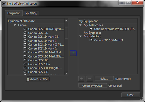
Figure 57: The Equipment tab of the Field of View Indicators window.
To the left, you will see the equipment database list, including selections for Telescopes, Eyepieces, and Detectors. To select a telescope, expand the Telescopes portion of the tree. You will see a large selection of telescope makers. Expanding a telescope maker’s menu will produce a list of telescope models by that manufacturer. Choose your telescope from the list. Once you have selected your telescope, click the green arrow button found in the middle of the window. You will then see the telescope listed on the My Equipment list to the right of the window.
Now, choose your eyepiece and/or detector from the appropriate menu from the left side Equipment Database.
If your model camera, eyepiece, lens or telescope is not listed, click this button to download the most recent equipment databases available from the Software Bisque web site, then check the appropriate Equipment Database to see if your hardware has been added since you installed your software.
If your equipment still does not appear, post a question on the Software Bisque community forums with the exact make and model of your equipment, and we’ll try to update our databases.
Once you have chosen your telescope, eyepieces, and detectors, click the Create my FOVIs button. You will then be taken to the My FOVIs tab, where each FOVI will appear in a list with a checkbox to turn each FOVI on or off.
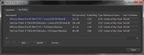
Figure 58: The My FOVIs tab.
Selecting a FOVI and clicking the Edit button will show the Add/Edit Equipment window where you can edit each element and aspect of the telescope and eyepiece or detector combination (page 130).
Clicking the Quick Add button also opens the Add/Edit Equipment window, in which you can add a FOVI with characteristics of your choosing. Just input the desired Shape, Reference Frame, and Width and Height in arcminutes, and you have added a brand new FOVI of custom dimension.
Clicking Remove will remove a FOVI from the list. Clicking Center will center the FOVI on the screen.
Checking the Preview checkbox will reveal a preview of each selected FOVI in the Sky Chart. When the Preview checkbox is turned on, the currently selected FOVI is centered on the Sky Chart. This lets you quickly determine which optical system is best for your needs.
|
|
Note that if you turn on both the Preview checkbox and the checkbox next to a FOVI, two identical FOVIs will appear on the Sky Chart (the “preview” FOVI and the actual FOVI). To avoid confusion, make sure to turn off the Preview checkbox before closing this window. |
|
|
Remember that FOVIs represent the view through your telescope and will not appear on the Sky Chart if the chart’s field of view is set to 100° (naked eye) and wider. To see the FOVIs, zoom to a field of view of less than 100°. |
The My FOVI tab shows the following information for each field of view indicator.
The FOVI description is the combination of the telescope and the eyepiece or detector description. To change a description, highlight the FOVI in the list and click the Edit button.
The size column shows the angular dimensions of the FOVI, in arcminutes.
For telescope and camera FOVIs, the scale or image scale, in arcseconds per pixel is displayed. The optical system’s magnification is displayed when the FOVI consists of a telescope and eyepiece.
The Type column shows either Eyepiece for eyepiece plus telescope combinations, or CCD for a camera plus telescope FOVI.
This column shows the frame of reference to use when displaying the FOVI. See “FOVI Frame of Reference (Reference Frame List)” on page 132 for details about reference frame options.
This column allows you to establish a link between a field of view indicator and your rotator hardware. When linked to an active rotator, the position angle of the FOVI as it appears on the star chart will be adjusted to match the current position of the rotator.
Conversely, the rotator hardware to may be commanded to move to a new position by dragging a linked field of view indicator.
Telrad™ finder FOVIs are shown at all fields of view (but may not be completely visible at small fields) and can be added to the Sky Chart using the My Chart Elements command on the Input menu.
1. Click Input > My Chart Elements.
2. On the Manage tab, click the Add Telrad button.
3. Under Command+Click (Mac) or Ctrl+Click (Windows), select Cursor Position in the Snap To pop-up menu.
4. Position the mouse cursor over the Sky Chart, press and hold the z key on macOS or the CTRL key on Windows, then click the left mouse button. A new Telrad finder is drawn at the current cursor position.
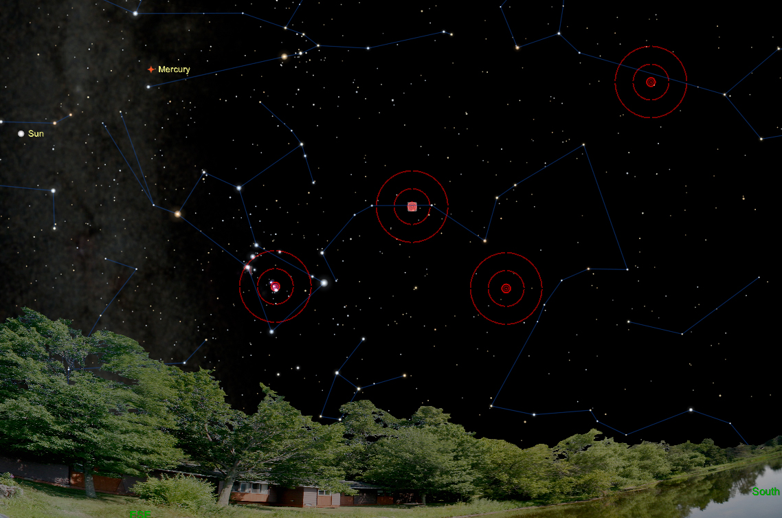
Figure 59: A Sky Chart showing multiple Telrad finders.
1. From the Manage tab on the My Chart Elements window, highlight the Telrad you want to move in the My Chart Element list by clicking on it or click on the center of the Telrad Finder on the Sky Chart. A selected Telrad finder appears as My Chart Element # in the Object Information Report on the Find window.
2. Click the Edit button (or double-click on the element) to show the Add/Edit Chart Element window.
3. To enter equatorial coordinates, click the Equatorial radio button then enter the right ascension (RA) in hours, minutes and seconds and declination (Dec) in degrees, minutes and seconds.
To enter horizon coordinates, click the Horizon radio button then enter the azimuth (Azm) in hours, minutes and seconds and altitude (Alt) in degrees, minutes, and seconds.
To Drag and Move a Telrad Finder:
1. From the Manage tab on the My Chart Elements window, select the Telrad you want to move in the My Chart Element list, or click on the center of the Telrad Finder on the Sky Chart. A selected Telrad finder appears as My Chart Element # in the Object Information Report on the Find window.
2. Click and drag the small red rectangle in the center of the Telrad finder to move it.
3. Release the mouse when the Telrad is positioned where you want it.
Clicking the Edit button or the Plus Sign button on the My FOVIs tab (Field of View Indicators window) shows the Add/Edit Equipment window. This window lets you define up to twenty different FOVI elements.
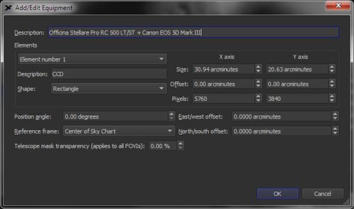
Figure 60: The Add/Edit Equipment window (clicking the Edit button).
Enter a description for your detector, such as Super CCD with 10 Detectors.
Up to twenty separate FOVI elements can be defined for each FOVI. For example, if your camera has a built-in autoguider, then the FOVI will have two different elements, one for the imaging detector and one for the autoguider.
Enter a text description for the element, such as “ST-237 guider mounted to my guide scope”.
Specify the shape of the element. An element can be:
· Circular (or elliptical)
· Rectangular
· Marker (a small cross that is offset from the main FOVI)
· Off-Axis Guider (a rectangle that represents the position of an off-axis guider).
When a FOVI element’s Shape is defined as Off-Axis Guider, enter the position angle of the off-axis guider, in degrees.
Enter the position angle, measured counterclockwise from north, of the FOVI element. This is the native position angle of the FOVI before any offsets due to a linked rotator are applied, so this value may be changed freely without effecting the position or orientation of linked hardware.
This field is automatically populated with the correct angle for FOVIs generated from a successful Image Link (page 322), allowing users to accurately predict the position and orientation of their imaging system's actual field of view. For FOVIs linked to rotators, it is recommended that this field be set to 0 degrees, and the position angle of the FOVI instead synchronized to the imaging system's actual field of view using the rotator offset (page 717).
To rotate a FOVI on the Sky Chart
Clicking on the FOVI line reveals two small red “handles” to indicate it is selected.
· Click and drag the center handle to unpin it from the center of the window and pin it to a specific RA/Dec position on the Sky Chart.
· Click and drag the outer handle to rotate the FOVI about its center.
· The FOVI’s current position angle is also displayed.
Hint: When accurate FOVI position angles are required, the FOVI’s position angle can be adjusted by one-tenth of one-degree increments by clicking and dragging the mouse cursor away from the center of the FOVI. When the cursor is positioned further from the center of the FOVI, small changes in the mouse position results in small changes to the FOVI’s position angle.
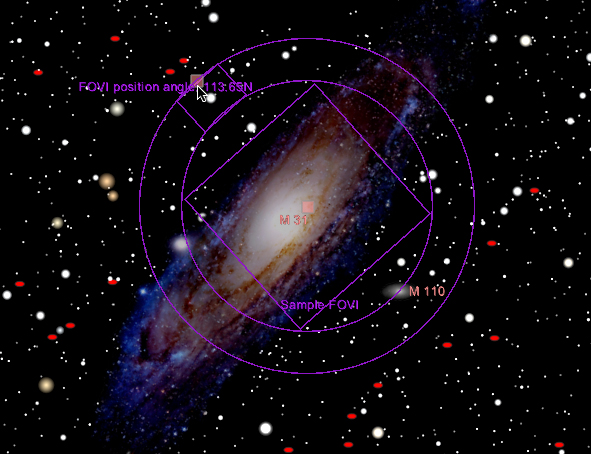
Figure 61: Click and drag on the small red square to change the FOVI’s position angle.
Select the frame of reference for the detector or detector/telescope combination.
· Sky Chart: The FOVI is pinned to the center of the Sky Chart.
· Equatorial: The FOVI is displayed specific equatorial coordinate.
· Telescope Crosshairs: When connected to a telescope, and the field of view 35º and smaller, the FOVI is displayed with the telescope crosshairs symbol in the center of the FOVI. At wider fields of view, only the telescope crosshair appears (two concentric yellow circles).
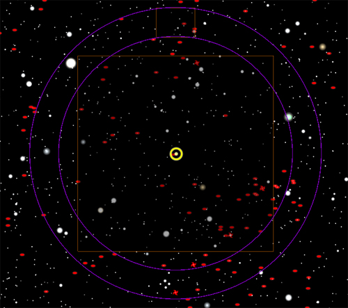
Figure 62: Sky Chart showing a Telescope Crosshairs FOVI at fields of view 35° and smaller.
· Telescope Mask: Use this option to simulate the view through a telescope. Regions outside the FOVI are “masked” and therefore not visible.
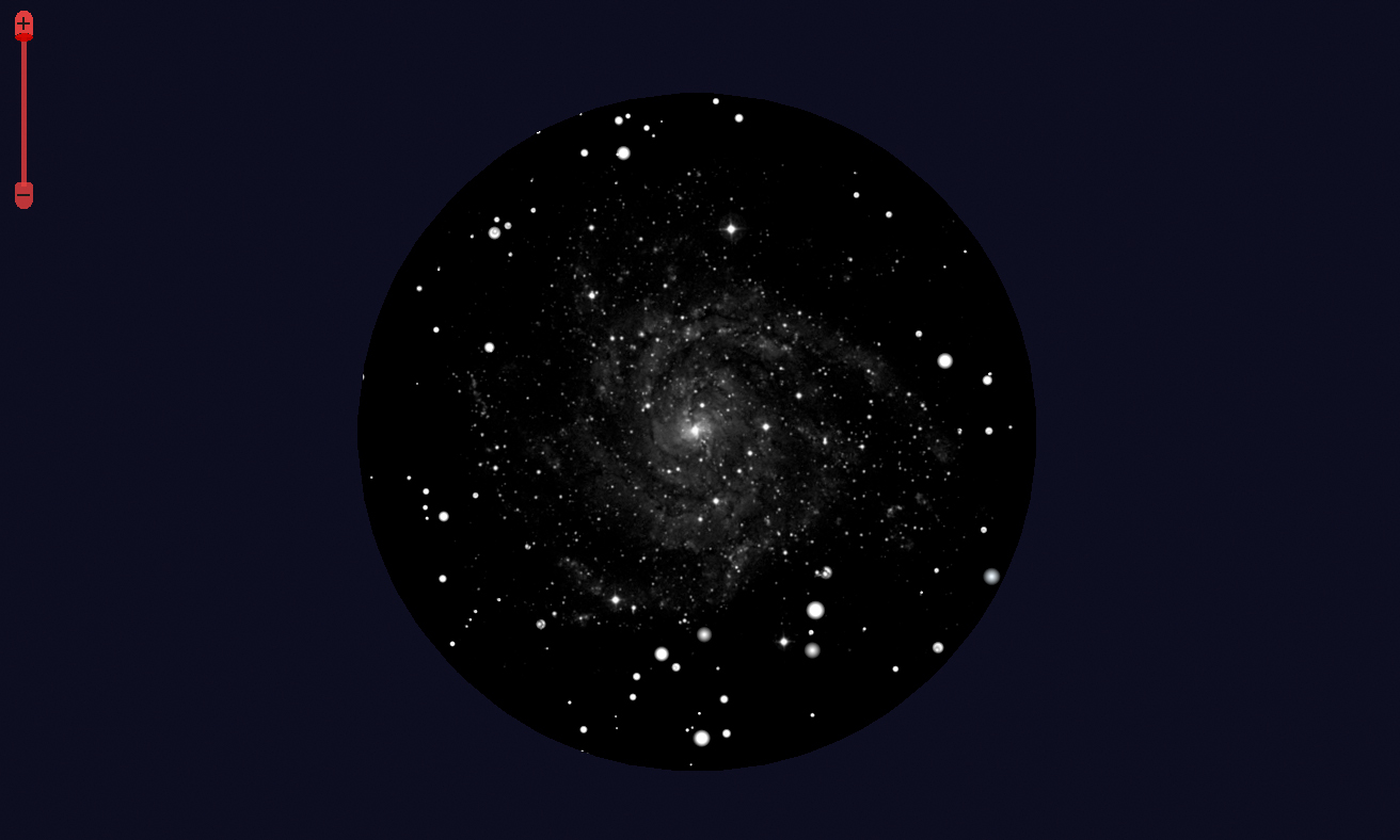
Figure 63: A Sky Chart showing a telescope mask FOVI.
Enter the physical size of the camera’s detector, in mm.
Enter the offset of the element from the Element Number 1, in mm.
For CCD cameras, enter the number of pixels in each axis. This value is used to compute the scale of images acquired with the camera, in arcseconds/pixel.
Specify the number of arcminutes to shift the center of the FOVI to the East or West. A number greater than zero shifts the FOVI West, a negative number shifts it East.
Specify the number of arcminutes to shift the center of the FOVI to the North or South. A number greater than zero shifts the FOVI South, a negative number shifts it North.
Clicking the Plus Sign button shows slightly different options.
Figure 64: The Add/Edit Equipment window (clicking the plus sign button).
Enter the FOVI’s Description, Shape and Reference Frame (described above) and the Width and Height, in arcminutes.
FOVIs that are displayed on the Sky Chart are configurable and customizable.
They can be:
· Clicked and dragged to any part of the screen
· Copied and “pinned” to a specific equatorial (RA/Dec) coordinate
· Rotated to any angle
· Used as the telescope crosshairs
· Used to create a telescope mask
· Used to control a camera rotator
Select the FOVI on the Sky Chart by clicking on it, or click on the center marker (if the FOVI has a visible center marker). Two small reddish squares, and the position angle, appear when the FOVI is selected. The center square can be dragged to move the FOVI; drag the outer square to change the position angle.
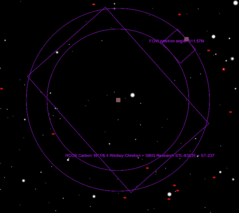
Figure 65: Clicking on a FOVI shows the position angle, and rectangles to position and orient it.
1. Click the Field of View Indicators command from the Display menu.
2. Click on the My FOVIs tab.
3. Highlight the FOVI that you want use as the telescope crosshair.
4. Click the Edit button.
5. On the Add/Edit Equipment window, select Telescope from the Reference Frame list.
6. Click OK.
When the Sky Chart’s field of view is small enough to resolve the FOVI, and the telescope is connected, the telescope’s crosshair will include the FOVI, too.
