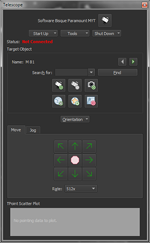
The Telescope window holds the most used commands when controlling a telescope. From the Display menu, click the Telescope command to show it.
Figure 177: The Telescope window (Display menu > Telescope command ).
Not all telescope mounts have the same feature set; the Telescope window contains options found in most go to mounts. Note that the commands in the Start Up, Tools, and Shut Down pop-up menus at the top of the window are mount specific and may contain different commands for different mounts.
Manufacturer-specific telescope control features can be accessed from the appropriate <Telescope Name> command in the Display menu. For example, the control system specific commands for the Gemini controller can be found on the Gemini window.
The Telescope window’s Start Up pop-up menu shows mount-specific commands that are used to connect to, synchronize, unpark or find the mount’s home position (where supported).

After setting up the mount’s communication with the computer (using serial, Wi-Fi, Ethernet communications), use this command to establish communication between TheSky and the mount. (Clicking Telescope > Connect does the same thing.)
See “Linking To and Synchronizing the Telescope” for more information about this command.

The “home position” establishes a mount’s mechanical orientation. Where supported, this command tells the mount to slew to its home position so that the control system knows where the mount is pointing.

Use this command to tell TheSky where the telescope is currently pointing. See “Software Synchronization” for more information about synchronization.

Shows the Telescope Setup window. See “Telescope ” for more information about setting up your mount.
Once communication with the telescope is established, the Telescope window can be used to find objects, monitor the status of the communications between the mount and the computer, initialize the mount’s hand paddle or controller with TheSky’s location, date, time, and time zone values, methodically slew the telescope outward to search for a nearby star and more.
The Tools pop-up menu contains the commonly used telescope control features.


Use the Turn Sidereal Tracking On and Turn Sidereal Tracking Off commands to enable or disable sidereal tracking on mounts that support this feature.
Use this command to enter a specific right ascension and declination or altitude and azimuth coordinate.
Use this command to slew the telescope to its previous coordinates. For example, if you slew to M42, then to the Pleiades, selecting the Slew Prior command will return the mount to M42. Slews must have been initiated by TheSky for this command to work. In other words, using the telescope hand paddle to slew to an object, then attempting to slew to the previous object will not work.
The Star Search feature slews the telescope in a spiral pattern of increasing size to help locate an object in the eyepiece. Choose the Star Search command from the Tools pop-up on the Telescope window to show the Star Search window.
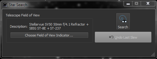
Figure 178: The Star Search window (Tools menu on the Telescope window).

Clicking this button begins slewing the telescope in a “spiral” pattern, based on the size of the selected Field of View Indicator.
The angular distance between slews when the telescope “spirals” outward can be configured to match the telescope’s field of view. Click the Select From Field of View Indicators button to tell TheSky the specifics of your optical system.
The Communications Log command (Tools pop-up menu on the Telescope window) shows the serial or network communications between TheSky and the telescope.
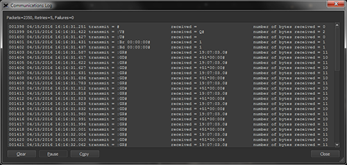
Figure 179: The Communications Log window.
The report contains six columns.
· Packet Count: The total number of packets or commands sent to the telescope, including retries and failures.
· Date and Time: The date and time the packet was sent.
· Transmit: The telescope-specific command that was sent to the telescope. Please refer the telescope protocol specifications for your telescope to decipher what each command means.
· Received: The response received from the telescope.
· Number of Bytes Received: The number of individual characters received.
This information can be useful when troubleshooting telescope connection problems.
The number of Packets represents the individual commands that have been transmitted to the telescope. If the telescope does not respond to a command, TheSky resends or Retries to send the command three times. Failures mean the telescope did not respond to a command. Multiple failures usually indicate that there is a configuration, cabling or other hardware problem. To begin troubleshooting, check that the telescope is turned on, the serial cable plus the USB to serial cable is properly plugged in to the computer and the telescope’s communication port.
Click the Clear button to clear the current report.
Click the Pause button to temporarily stop the communications log report from being updated. Note that communications with the telescope continue when this button is pressed down.
Astro-Physics, Celestron, iOptron, Meade and other mounts allow TheSky to configure the control system’s location, date, time and time zone information, rather than having to set them manually using the hand paddle. From the Telescope window, click Tools > Location, Date, Time Telescope window to show the Telescope Location, Date, Time window.
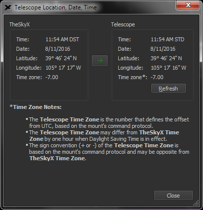
Figure 180: The Telescope Location, Date, Time window (Tools menu on the Telescope window).
For the telescope to be commanded to the correct coordinates, the telescope must use the same parameters as TheSky.
Click the Refresh button to get the telescope’s current settings.
Click the green arrow button to configure the hand paddle’s settings to match TheSky’s current time, date, latitude, longitude, and time zone settings.
TheSky’s settings may not exactly match the telescope’s settings for the following reasons.
|
Parameter |
Reason for Difference
|
|
Time |
The time display is not updated continuously on this window, so the seconds may differ.
|
|
Latitude and Longitude |
The telescope protocol may not allow arcsecond accuracy for latitude and longitude. The telescope’s coordinate convention may differ from TheSky’s convention. For example, the Astro-Physics longitude is displayed from 0–360°; TheSky measures longitude from 0–180° East or West of GMT.
|
|
Time Zone |
TheSky uses a different time zone sign convention as compared to the telescope protocol, so the sign of TheSky’s time zone is opposite from the telescope. TheSky sets the telescope’s time zone to the nearest whole number. When Daylight Saving Time is in effect, the telescope protocol must be configured to use a one hour offset from the actual time zone. This convention means TheSky’s time zone will differ from the telescope by one hour. |
These differences are normal and expected and ensure the telescope is properly configured for TheSky control.
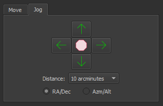
Figure 181: The Jog pane on the Telescope window.
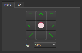
Figure 182: The Move pane on the Telescope window.

Paramount Robotic Telescope Systems (page 449) use the Bisque Telescope Control System (Bisque TCS) for dual axis motion control. The Bisque TCS command provides access to control system specific features. See the Paramount User Guide for Bisque TCS documentation.
The Virtual Mount window simulates the orientation and motion of your mount and can be especially helpful for monitoring and troubleshooting remote mount operation. As the actual mount is commanded to slew, the simulated, virtual mount follows.
The current simulated mounts include:
· Astro-Physics Mach1 GTO
· Software Bisque Paramount ME
· Software Bisque Paramount MX
The simulated telescope on the simulated mount is a Newtonian optical tube assembly shown in Figure 183. We hope to add other simulated mounts and telescopes in future versions of TheSky.
Choose the Virtual Mount command from the Tools pop-up on the Telescope window to show the Virtual Mount window.
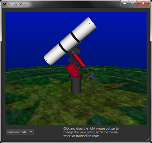
Figure 183: The virtual Paramount MX mount with a refractor.
Right-click and drag on the Virtual Mount window to change the point of view. Place the mouse cursor over this window and use the mouse scroll wheel to zoom in and out.
The pop-up menu on the bottom of the Virtual Mount window allows you to select the simulated telescope mount.
Use the controls on the Move and Jog tabs to manually slew or move, by discrete increments, the telescope.
Click and hold the Move arrow buttons on the Telescope window to direct the telescope in a specific direction. The Rate pop-up menu controls the speed of the slew. The Rate options in this list change depending on the currently selected mount.
The Move window offers eight different direction controls: north, east, south, west, and the “diagonal” directions in between. Diagonal direction buttons are hidden for mounts that do not support dual-axis moves.
Use these arrow buttons to slew the telescope by the angular distance shown in the Distance list, and using and equatorial (RA/Dec) or horizon (Azm/Alt) coordinates.
The direction a button moves the mount is configurable. This is useful, for example, when the optical tube on a German equatorial mount changes sides from East to West, the relative motion of the telescope in the right ascension axis is reversed. Changing the orientation for the right ascension axis makes the buttons work “as expected” for the opposite side of the mount.
· Normal sends the standard commands to the mount for moving in this direction.
· Swap Axes changes the left/right direction buttons to up/down, and up/down to left/right.
· Flip Left/Right swaps the left and right buttons. Left moves right, and right moves left.
· Flip Up/Down swaps the up and down buttons. Up moves down and down moves up.
Alice, welcome to Wonderland.
At the end of the night, you’ll want to make sure to park the telescope so it will be in the correct orientation to close the observatory roof. Note that some telescope control systems cannot park the telescope. For these telescopes, TheSky uses a “built-in” park feature that slews the mount to the park position (a fixed altitude/azimuth coordinate) that you define and turns off the mount’s sidereal tracking. When communication with the mount is established again, TheSky can unpark the mount and initialize the mount’s control system.

Use this command to specify the altitude and azimuth coordinates to slew the mount before parking. The current position of the telescope crosshairs is used as the park position.

Use this command to delete the previously defined park position. After clearing the park position, a new one must be defined with the Set Park Position command before the telescope can be parked.

The Park command slews the telescope to the park position, and then turns the mount’s sidereal tracking off (where possible).

Once a mount has been parked, it may have to be unparked to initialize the telescope control system to restore normal operation.
Terminates communication with the mount. This command is the same as selecting the Connect command from the Telescope menu when there is a connection. See “Linking To and Synchronizing the Telescope” for more information about this command.
Star synchronization (or “sync” for short) a mount with TheSky initializes the mount’s control system to an equatorial position on the celestial sphere. Mount synchronization may be performed using the mount’s hand paddle, if one is available, or through software synchronization.
1. For telescopes that employ an external hand paddle that can control the mount independently, make sure that TheSky’s location, date, time, time zone and Daylight-Saving Time settings (DSO) match the telescope’s hand paddle settings. See “Entering Your Location” on page 36 for information about how to configure TheSky for your location on earth. See “Location, Date, Time” on page 392 for details how to use TheSky to configure the mount’s site and time settings.
If your mount does not have a hand paddle, or the Location, Date, Time command is not available for your telescope, consult the owner’s manual for your mount for details how to initialize the control system before using TheSky to control it.
2. From TheSky, manually center a known star in the telescope’s eyepiece (or other detector) using the mount’s hand controller or TheSky’s telescope move control commands (see “Move and Jog Controls” on page 396).
3. Find or identify this star in TheSky Professional. (See “Finding and Identifying Celestial Objects” on page 62).
4. Choose the Star Synchronization command from the Start Up pop-up menu on the Telescope window.
5. Click the Sync button.
The following procedure applies if your telescope can be synchronized through software like TheSky. Some control systems do not support software synchronization and must be configured to operate “standalone” first. If your telescope mount does not support software synchronization, following the manufacturer’s initialization instructions now. TheSky can control the mount only after it has been initialized using the hand paddle.
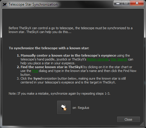
Figure 184: The Telescope Star Synchronization window (Synchronize command in the Start Up pop-up menu on the Telescope window).
1. Select the Connect command from the Telescope menu. Crosshairs appear on the Sky Chart, showing the position the telescope “thinks” it is pointing.
2. If you haven’t set the telescope’s time and coordinates, do so now (page 392).
3. Position the center of the telescope’s field on a known star. In general, do not select a planet, nebula, galaxy or other “extended object” for synchronization; star coordinates are typically more accurate, and a star is a true “point source.”
4. Click on the same star if it is visible on the Sky Chart or use the Find command to locate it.
5. Click the Star Synchronization command in the Start Up pop-up menu on the Telescope window.
6. On the Star Synchronization window, click the Sync button.
The Sky Chart’s crosshairs should jump to and overlay the star that was used for synchronization, or be centered on the star used during the hand paddle initialization.
The telescope is now aligned on, or synchronized with, the target object and can be controlled by TheSky. See “Slewing to a Specific Object or Target” on page 403 to get started slewing the telescope.
Use the Sync command to perform a synchronization on the current target object. This command bypasses the Star Synchronization window.
The Sync action should not be performed unless you are sure of the consequences.
· Once a permanently mounted Paramount-class mount is polar aligned and a working TPoint model established, further synchronization should not be necessary. A “bad” synchronization can cause the mount to lose its orientation with the celestial sphere.
· Telescopes that employ TPoint should only be synchronized before pointing calibration data is acquired. Subsequent observing sessions should recalibrate the model rather than re-synchronize the mount.
· If there is no TPoint model, then you may wish to “single-click” synchronize the mount multiple times during a single observing session to minimize pointing errors in a small area of the sky.
To add the Sync command to a toolbar:
1. On the Preferences window, click the Toolbars icon (page 206).
2. Click the Customize button to show the Customize Toolbars window.
3. Select the toolbar to add an action.
4. Select the Sync command from the Actions list, under All Other Commands.
5. Click the right arrow to add this action to the selected toolbar.
6. Click OK.
7. Click Close.
The single-click Sync command is now accessible on the selected toolbar.
If you are familiar with TheSky6 Professional Edition, you may have used the Image Link and Sync feature, where the coordinates of a photo determined by Image Link are used to synchronize the telescope. TheSky Professional can do the same.
Follow the steps below to use a photo from a previous session to reestablish the telescope’s position.
1. Use the Image Link command to overlay a photo on the Sky Chart and determine the astrometric coordinates for every position in the photo (page 322).
2. Click on the Sky Chart anywhere “inside” the boundaries of the Image Link photo. The first object in the Related Search Results list on the Details tab of the Find window is named < OBJECT FITS Keyword> Image Link Photo, where <OBJECT FITS Keyword> is the text from the OBJECT keyword in the photo’s FITS header. The coordinates of the Image Link photo are the 2000.0 astrometric RA/Dec of the center of the photo. Synchronizing on the Image Link photo restores the telescope’s position to these coordinates.
3. Synchronize the telescope on this target (page 398).
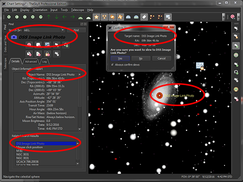
Figure 185: Clicking the Image Link photo on the Sky Chart displays the photo’s OBJECT name in the FITS header, plus Image Link Photo in the Related Search Results of the Find window.

1. Click on the object in the Sky Chart. If the desired object is not visible on the current chart, click the Find command from the Edit menu, enter the object’s name (Crab Nebula, for example) or its catalog number (M1) into the Search For text input and click the Find button.
2. Click the Slew button. One is located on the Telescope, Find and the Observing List windows and on the Telescope toolbar.
The Search For text input and Find button are also available on the Telescope window.
There’s another way slew the telescope…
1. Click on an object to identify it.
2. Right-click over the object on the Sky Chart.
3. Select the Slew command from the Sky Chart’s pop-up menu.

In progress telescope slews can be immediately stopped by clicking the Abort Slew button on the Telescope window or on the Telescope Toolbar (page 205).
Alternatively, right-click on the Sky Chart, and click the Abort command.
Astronomers know better than to claim stars do not move. Proper motion, precession, nutation, aberration and other phenomena cause astronomical bodies to move over time when observed from earth.
While TheSky makes every effort to hide the complexities involved with coordinate transformations in cataloged data, and generally uses the object’s topocentric coordinates, you may still need to slew a telescope to coordinates that were recorded at a different time. For example, older astronomical catalogs may have recorded in equinox 1950. Slewing the telescope to equatorial coordinates that are from 1950, when TheSky is expecting positions from a different equinox, means the telescope will point to the wrong position.
Use the Slew To Coordinates command from the Tools menu on the Telescope window to display the Enter Coordinates tab of the Navigate window. From here, enter the right ascension, declination or azimuth, altitude coordinates, then click the Slew To RA/Dec or Slew To Az/Alt button, respectively.
When using coordinates from historical observations, make sure to specify the equinox of the coordinates by entering the year into the Equinox list box, or choosing one of the default options: Apparent, 2000.0, or B1950.0. Or manually enter a different value if the coordinated are from a different equinox.

Use the Slew Prior command to slew the telescope to the previous target. This command is not accessible on the Telescope window but can be added as a button to any tool bar. See “Customizing Toolbars” on page 206 for details about adding buttons to toolbars.
A telescope can be slewed to the coordinates that match the center of an Image Link photo so that its position can be restored from night to night.
1. Use Image Link or All Sky Image Link to find the astrometric solution for a photo. After a successful Image Link, the photo will be overlaid on the Sky Chart, precisely matched against the background stars. Make sure to turn on the Show Linked Photo checkbox on the Image Link window to make the photo visible.
2. Click within the Image Link photo on the Sky Chart to identify it. This target object appears in under Related Search Results on the Object Information window with the name < OBJECT FITS Keyword> Image Link Photo, where <OBJECT FITS Keyword> is the text from the OBJECT keyword in the photo’s FITS header (or DSS Image Link Photo when the photo was obtained from the Digitized Sky Survey data).
3. Select the Image Link Photo text to make it the current target object, then click the Slew button to slew the telescope to J2000.0 RA/Dec of the photo’s center.

Imagine, while observing objects visually with your go to telescope, slewing the telescope to a star cluster (the “target”) in a different part of the sky. Chances are, the telescope’s inherent pointing inaccuracies mean the cluster will not fall “dead center” in the eyepiece. At this point, you will most likely grab the telescope’s hand paddle to manually find and center the object in the eyepiece before enjoying the view.
A Closed Loop Slew automates this target centering process using the astrometric position of a photo acquired with a camera, instead of the human eye. Image Link (page 322) replaces the observer’s interaction with the telescope to automatically center the target object. The result of a closed loop slew is that, using a single button click, a go to telescope with a camera attached can be slewed to any target, or equatorial coordinate, and the object will fall squarely in the center of the frame.
This feature can be used, for example, to precisely slew the telescope to a specific star so that it falls on a spectrographic slit each night. Or, to precisely slew the mount to the center of a previously acquired photograph.
The Closed Loop Slew command incorporates automated telescope control, automated Image Links and automated camera control to ensure the target object is centered.
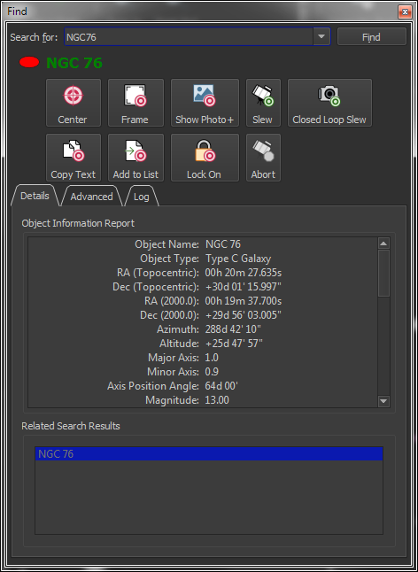
Figure 186: The Closed Loop Slew button on the Find window.
Figure 187 shows what happens “behind the scenes” when the Closed Loop Slew button is clicked. 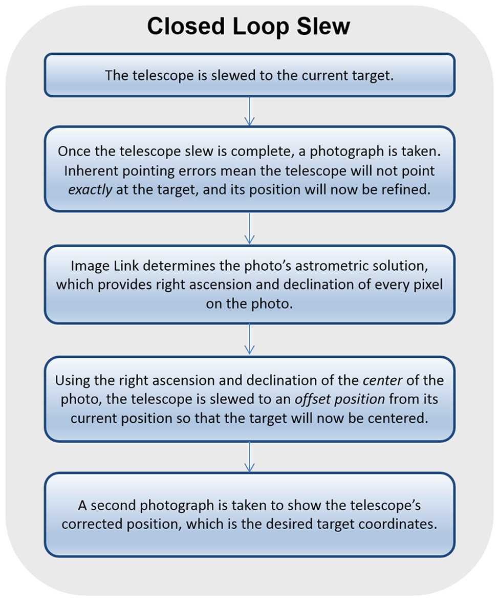
Figure 187: Flow chart showing each step of a Closed Loop Slew.
Acquiring multiple photos, and determining the astrometric solution necessarily requires more time than the typical “open loop slew”, however, the result of a Closed Loop Slew means the target object should be centered on the photo to within a few arcseconds of the target’s right ascension and declination coordinates.
To access the Closed Loop Slew settings,
1. Click Tools > Image Link and open the Setup tab.
2. Click the Automated Image Link Settings button to display the Automated Image Link Settings window.
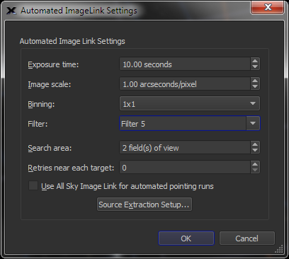
Figure 188: The Automated Image Link Settings window.
Enter the length of the exposure, in seconds of time, to use when performing a Closed Loop Slew.
Enter image scale, in arcseconds per pixel, of the camera and optical system used to perform the Closed Loop Slew.
Select the camera’s bin mode during Closed Loop Slews.
Select the filter to use during Closed Loop Slews.
Enter the size of the sky region to search for an Image Link match during the Closed Loop Slew.
Specify the number of times to retry performing a Closed Loop Slew at a given position before displaying a failure error message.
When this check box is turned on, Closed Loop Slews use All Sky Image Link instead of the classic Image Link (See page 346 for a comparison of these technologies) to determine the astrometric solution.
Click is button to specify the Source Extraction settings (page 329) to use for Closed Loop Slews.
All other camera-specific settings used when acquire photos from the imaging camera during a Closed Loop Slew (including bin mode, image calibration, etc.) can be configured from the Camera tab (page 550). Closed Loop Slews do not use the autoguider settings.
|
|
When the camera’s binning (page 569) is changed, the value of the Image Scale on the Automated Pointing Calibration Run window must be changed accordingly.
For example, if the image scale produced by the optical system at 1x1 binning is 1 arcsecond per pixel, and the binning is changed to 2x2, then the value in the Image Scale text box must be changed to 2 arcseconds per pixel. Failure to do so will cause the Closed Loop Slew’s Image Link to fail. |
|
|
The Automatically Save Photos checkbox must be turned on before performing a closed loop slew. If this option is turned off, the initial photo is not saved automatically, and the Image Link portion of the closed loop slew process will fail with the error message: “Error 507. Please save the photo.” |
Once TheSky Professional has been configured for your mount (page 375) and imaging camera (page 559), click the Closed Loop Slew button to connect to the mount and the camera, then slew to the telescope to the target (using the Closed Loop Slew process described above).

TheSky Professional can slew the telescope to, and track spacecraft. The first step is to locate the satellite to track (by clicking its symbol on the Sky Chart or using the Find command), then click the Track Satellites button on the Telescope window (which is otherwise hidden). If the satellite is currently above the horizon, mount is slewed to intercept the satellite’s path, then the mount’s tracking rates are set to match satellite’s rates. If the satellite is currently below the horizon, TheSky waits until it is visible (specifically, above the local horizon) then begins the slew to and track satellite process.
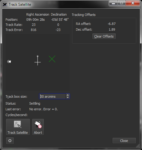
Figure 189: Tracking initiated, but not yet “stable”.
When then satellite appears above the theoretical local horizon, the mount slews to the satellite and begins tracking it. The satellite’s Position, relative Track Rate and Track Error in Right Ascension and Declination are displayed at the top of the window.
The black region represents the background sky. The white circle represents the satellite, the white arrow drawn through this circle shows the magnitude of the satellite’s tracking rate and its current trajectory. The gray crosshairs show the center of the field. The green X represents the current Tracking Offset that is applied to the mount’s position.
Optimal tracking is achieved when satellite is centered in the field. Mechanical errors and uncertainty in the satellite two-line elements may cause the satellite to fall away from the center. To adjust the position of the satellite, click in the black region away from the satellite’s current position. The green X shows this new offset, and, when the correct offset is applied, the satellite will slowly move to the center of the field.
A larger number in the Track Box Size text box allows a larger maximum tracking offset. Click the Clear Offsets button to set the offset to zero in each axis.
If for any reason the mount cannot continuously track the satellite, the message “Target lost, unable to maintain tracking. Error = 7501.” is displayed, and the mount’s tracking rates will be turned off.
Each control on TheSky Professional’s standard Satellite Tracking window is described below.
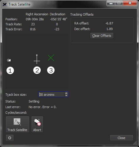
Figure 190: The Satellite Tracking window’s graphical controls.
Figure 190 shows numbers next to each graphical element, and each is described below:
· The white arrow (1) shows the relative position of the satellite in the field of view and points in the direction of the satellite’s motion.
· Click and drag the small circle at the end of the cross in the center of the graphic (2) to rotate the field (so that the satellite path can be oriented to match the video or detector).
· Click anywhere inside the black region (which represents a “satellite tracking field of view” or track box) to apply an offset to the telescope’s current tracking position, which is represented by a large green “X” (3).
Advanced satellite tracking capabilities for Paramount-class mounts are available in the optional Advanced Satellite Tracking module. Contact Software Bisque for details.
Shows the right ascension and declination coordinates of the telescope.
Shows an internal tracking rate for the satellite.
Shows the magnitude of the tracking error in each axis. The minimum “acceptable” average tracking error that is allows to start tracking can be configured from the Satellite Tracking options in the Advanced pane on the Preferences window (page 232).
Shows the offsets in right ascension and declination, in arcminutes that are applied to the satellite’s position during tracking. The offset is represented by the green X graphic. To change the offset, click the mouse within the black region.
Click this button to set the tracking offsets to zero.
Enter the relative size of the satellite tracking box. The size of the track box can be adjusted to match the field of view of the optical system. The track box size can be up to two arcminutes, so that relatively large “position offsets” to the telescope’s current track position can be introduced by clicking on the track box graphic.
Shows the current state of satellite tracking.
· Idle: No satellite tracking.
· Begin: TheSky has initiated satellite tracking.
· Start Slew: Telescope slewing is about to start.
· Waiting for Target to Rise: TheSky is monitoring the satellites position and will begin tracking when it rises.
· Slewing to Target: Telescope is being slewed to the satellite.
· Settling: The position of the telescope is being adjusted to match the satellite’s position.
· Tracking: The mount is successfully tracking the satellite.
Shows the most recent error message to occur.
Shows the frequency at which the satellite’s position is being updated.
Click this button to start tracking the selected satellite.
Click this button to stop tracking the satellite.
· TheSky Professional does not use a “leapfrog” or “successive slews” method to track satellites. Instead, TheSky sets the mount’s tracking rate in both RA and Dec to match the satellite’s tracking rate.
· Many commercial mounts do not allow tracking rates to be configured in both RA and Dec axis, so these mounts cannot be used to track satellites with TheSky.
· For mounts that can set dual axis tracking rates, many still do not have the required dynamic range to track very slow or very fast-moving satellites. Trying to use a mount that does not have configurable tracking rates from zero to several degrees per second may not result in satisfactory results.
· TheSky Professional’s satellite tracking has been optimized for, and extensively tested with both the Paramount ME and Paramount MX mounts and works quite well to accomplish this task. The Paramount control system allows tracking rates to be configured for both the RA and Dec axes and can track virtually any satellite (or any object that tracks at any rate from 0.0 arcseconds per second up to several degrees per second).

Click this button to center the telescope crosshairs on the Sky Chart.

Solar system objects, including the Sun, Moon, planets, comets, and asteroids each move at rates that can vary greatly compared to sidereal rate.
· Important Note: To track objects at non-sidereal rates using TheSky, the mount’s control system must be able to set tracking rates for both the right ascension axis and declination axis based on the computed rates of the object.
· See “Tracking ” on page 410 for details about tracking satellites with TheSky. Many commercial mounts either cannot set the tracking rates in both axes, or do not have sufficient dynamic range to track relatively slow moving or relatively fast-moving objects.
To configure the mount to track at the non-sidereal rate for one of these objects:
1. Locate the object on the Sky Chart (using either the Find command or by clicking the object on the Sky Chart).
2. Click the Slew button to slew the telescope to the object. This step is optional, but, if the object is a “faster mover”, it’s better to position the telescope close to its current position first.
3. Click the Set Track Rates button on the Telescope window. The Confirm Set Track Rate window shows the current right ascension and declination rates for the selected target, in arcseconds/second.
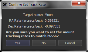
Figure 191: The Confirm Set Track Rate for solar system objects.
Clicking the Yes button sets the mount’s right ascension and declination tracking rates.
Slewing to a star automatically resets the right ascension’s axis to the sidereal rate and sets the declination rate to 0.0.
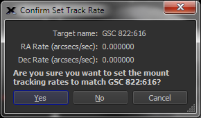
Figure 192: Set tracking rate to the sidereal rate.
Clicking the Set Track Rate button when the target object is a star shows 0.0 for both the right ascension and declination tracking rates, which, although perhaps confusing, is TheSky’s convention. The right ascension tracking rate is relative to the sidereal rate, so, setting a tracking rate of 0.0 in right ascension means “track at the sidereal rate”. As expected, the declination axis’ tracking rate is set to 0.0.

This feature requires, and is used by the TPoint module.
Click this button to add a pointing calibration sample to calibration data. See “TPoint ” on page 385 for details about telescope modeling.
Enter the name of a target object into the Search For text box then click the Find button. Or, click the mouse on the Sky Chart to select the target. If there is more than one object near the mouse cursor, click the forward or backward buttons to scroll through them.


Click the Flip Mount Now button to slew the telescope to the opposite side of the pier and still point to the same object. This can be convenient when a German equatorial mount is pointing to an object near the meridian and the telescope is on the west side of the pier.

Select the Connect command on the Telescope menu to stop communicating with the telescope and close the communications port.
The telescope simulator lets you connect to, synchronize, and slew a go to telescope without connecting to an actual mount. The telescope simulator lets you learn how to use TheSky to operate a telescope from TheSky or practice an observing session during daylight.
|
|
The telescope simulator, by design, has a limited feature set. Telescope initialization, synchronization, and slewing are possible let you get the feel for controlling a telescope with TheSky. It does not support all telescope control features. For example, you will need an actual mount to set non-sidereal tracking rates or simulate a mount’s orientation on the Virtual Telescope window (page 394). |
1. Select the Telescope Setup command from the Telescope menu.
2. In the Telescope Setup window, click the Select Mount button.
3. Choose the Telescope Mount Simulator option from the Simulator list.
4. Click OK.
5. Click the Connect button on the Telescope Setup window to establish a virtual connection to the simulated telescope mount.
TheSky’s Digital Settings Circles window displays a status report that contains, for example, the telescope’s RA/Dec coordinates. The text size is also configurable so that it can be more easily read at a distance.
This feature is available with both encoder-based systems and telescopes having full computer control.
To use it, select the Digital Setting Circles command from the Telescope menu.
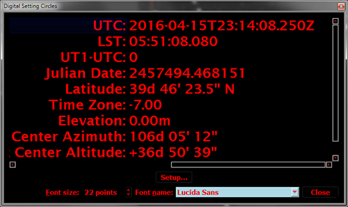
Figure 193: Digital Setting Circles window.
By default, the report shows universal time (UT) and local sidereal time (LST). Click the Report Setup button to show the Digital Setting Circles report in the Preference window.
Select the attributes you wish to display in the report, and then click Close.

