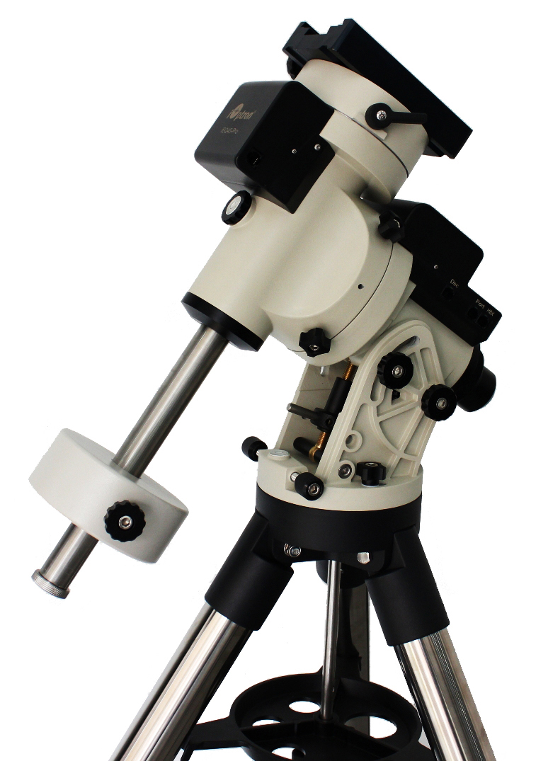
Figure 201: The iOptron EQ45 Pro German Equatorial Mount. ã iOptron.
TheSky can control iOptron™ model altitude/azimuth and equatorial mounts. For the best experience, install the latest mount firmware. (Your hand paddle’s firmware version can be viewed by pressing Menu button > Firmware Information.)
1. Visit https://www.iOptron.com.
2. Search the iOptron website for your mount model.
3. On the mount’s product page, click on the Support Documents tab, then click the Download Latest Firmware link.
4. Carefully follow the instructions to install the latest available HC, Main, RA, and Dec firmware versions.
|
Model |
Recommended Mainboard Firmware |
Comments |
Communication Port |
|
Cube II EQ mode |
080801 (2008-08-01) |
|
RJ11 RS232 |
|
Cube II AA mode |
080801 (2008-08-01) |
|
|
|
Cube Pro EQ mode |
190422 (2019-04-22) |
|
|
|
Cube Pro AA mode |
190422 (2019-04-22) |
|
|
|
SmartEQ Pro+ |
V20190424 (2019-04-24) |
|
|
|
CEM25(/P) |
V20190422 (2019-04-24) |
Do not use this firmware for the CEM25-EC |
|
|
CEM25-EC |
V20190422 (2019-04-24) |
This firmware is for the CEM25EC, only. |
|
|
iEQ30 Pro |
V20190424 (2019-04-24) |
|
|
|
CEM40 |
V210605 (2021-06-05) |
The firmware update process differs depending on the version of the hand controller (8407 or 8410).* |
|
|
CEM40-EC |
V210605 (2021-06-05) |
|
|
|
GEM45 |
V210605 (2021-06-05) |
|
|
|
GEM45-EC |
V210605 (2021-06-05) |
|
|
|
iEQ45 Pro EQ mode |
V20190424 (2019-04-24) |
|
|
|
iEQ45 Pro AA mode |
V20190424 (2019-04-24) |
|
|
|
CEM60 |
V20211018 (2021-10-18) |
|
|
|
CEM60-EC |
V20211018 (2021-10-18) |
|
|
|
CEM120 |
|
The firmware update process differs depending on the version of the hand controller (8407 or 8410).* |
|
|
CEM120-EC |
|
The firmware update process differs depending on the version of the hand controller (8407 or 8410).* |
|
Notes:
· The CEM40 and GEM45 models are physically connected to the computer using a USB cable instead of RS232 cable. The mount’s built-in FTDI-based USB adapter allows the operating system to map the USB port as a serial device (COM port). See the
· The CEM120 and CEM120-EC models includes an RS232 port, a USB port (same as on CEM40/GEM45), a LAN and a WIFI connection. Be sure to choose the CEM120 mount to control this model.
* The hand paddle version is displayed on the LED display at power up (Figure 202).
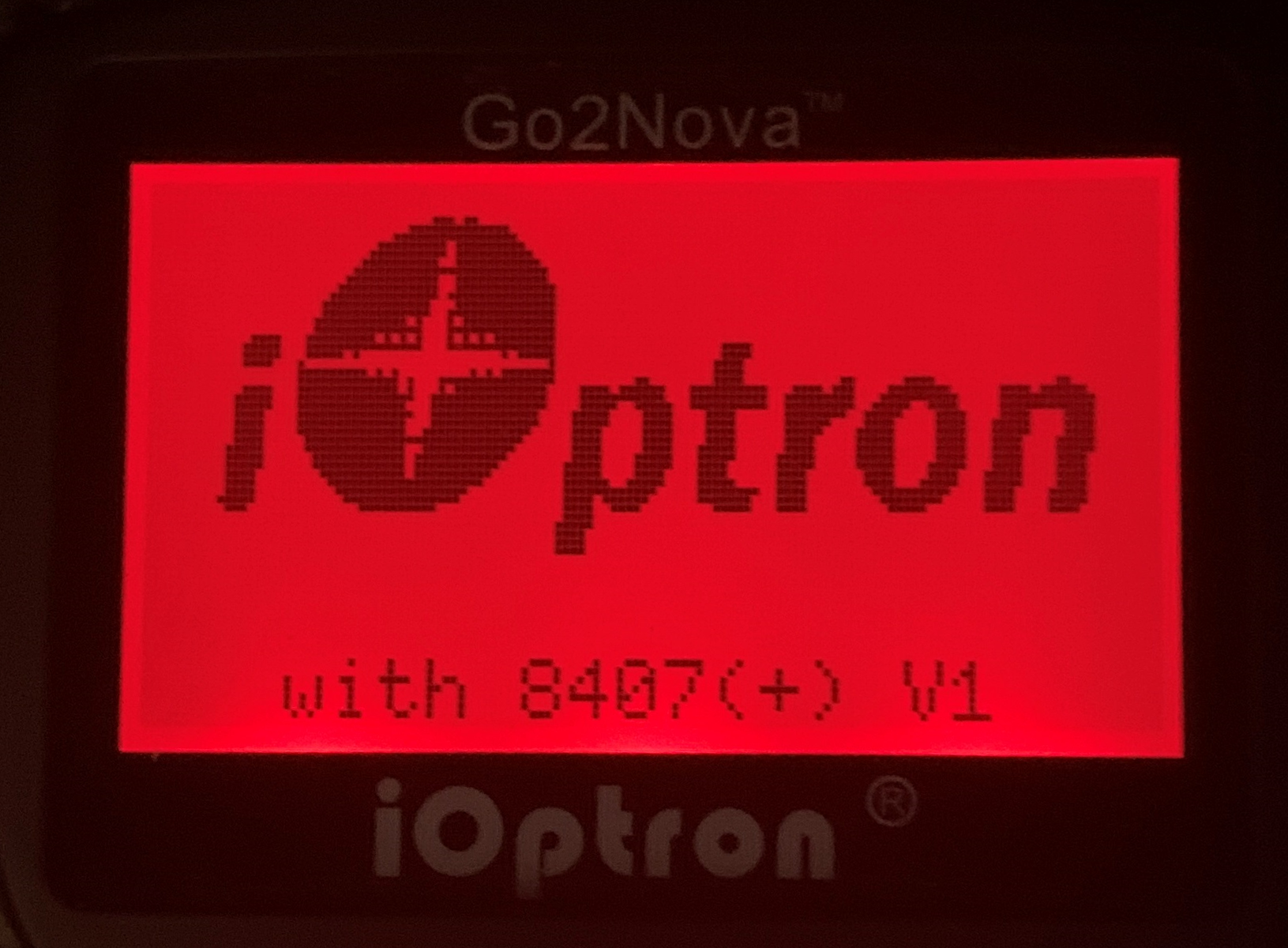
Figure 202: iOptron hand controller version (8407) is temporarily shown at the bottom of the LED display at power up.
· An iOptron GEM or Alt/Az mount.
· A standard RS232 cable or USB cable (supplied with mount). If your mount includes Wi-Fi, a Wi-Fi enabled computer. If your mount includes an Ethernet port, a computer connected to a network.
· A Linux, Mac, or Windows computer running TheSky Professional or TheSky Serious Astronomer.
· No software driver is required for iOptron mounts that use a serial (RS232) interface.
· Newer model iOptron mount that connect to the computer via a USB cable use a FTDI-based USB adapter and do not require installation of a separate serial port driver.
· Older model iOptron mounts that use a Silicon Labs USB UART require an operating system-specific Virtual Serial Port Driver that must be installed before TheSky can communicate with this mount. For example, early model SmartStar mounts use the Silicon Labs CP210X USB to UART Bridge computer chip for serial communications, and the driver can be downloaded from the Silicon Laboratories’ web site: http://www.silabs.com.
The USB to UART Bridge product page (and drivers) is:
http://www.silabs.com/products/mcu/pages/usbtouartbridgevcpdrivers.aspx
Download and run the above appropriate installer for your operating system to install the VCP driver.
Follow the steps below to connect the iOptron mount’s serial port to the PC.
1. Plug the phone-style jack of the supplied telescope serial cable (cable 1 in Figure 203) into the RJ11 port labeled RS232 on mount’s base, or into the RJ11 port located on the bottom of the hand paddle.
2. Plug the DB9 end of the telescope cable into the USB Adapter (cable 2 in Figure 203). USB adapters based on the Future Technology Devices International (FTDI) chipset are readily available on-line, inexpensive, work well on macOS, Linux and Windows and generally do not require installation of a separate software driver.
3. Plug the USB Type C end of the USB to serial adapter into a compatible port on the computer. If the computer does not have Type C connectors, add a Type C to Type B adapter (part 3 in Figure 203).
4. From TheSky, click Telescope > Telescope Setup.
5. On the Imaging System Setup window, double-click Mount, select your iOptron model mount and click OK.
6. On the Imaging System Setup window, click Mount Setup > Settings and select the name or number of the serial port.
If you are unable to locate the name or port number, make sure the operating system recognizes the USB adapter:
· On Windows, use the Device Manager app to show the list of COM ports that are recognized by the computer (Figure 207).
· On macOS, click Apple > About This Mac then click the System Report button on the Overview pane to view the System Report. On the System Report window, under Hardware, expand USB. On the right side of the report, under USB Device Tree, expand each node labeled USB 3.1 Bus to locate the USB Serial Converter (or similar description).
· On Linux, open the Terminal, and type dmesg | grep tty.
7. On the Imaging System Setup window, click Mount Setup > Connect to connect to the mount.
· 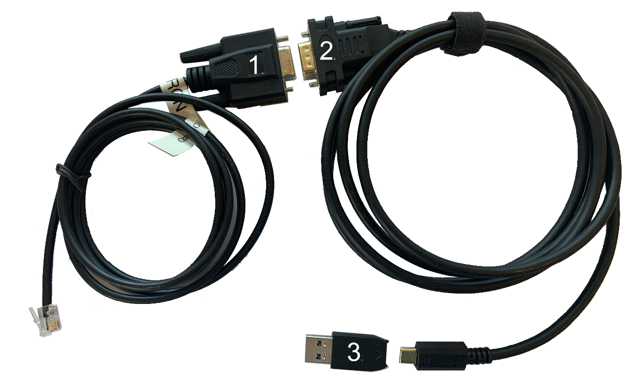
Figure 203: Cables used to directly connect the iOptron serial port to the USB port on the PC.
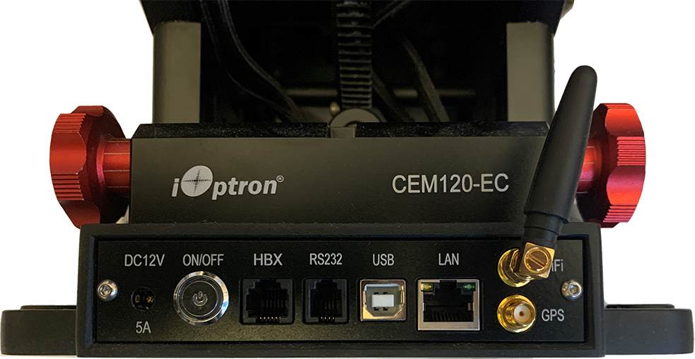
Figure 204: The RS232, USB, LAN ports on the base of the CEM120-EC mount.
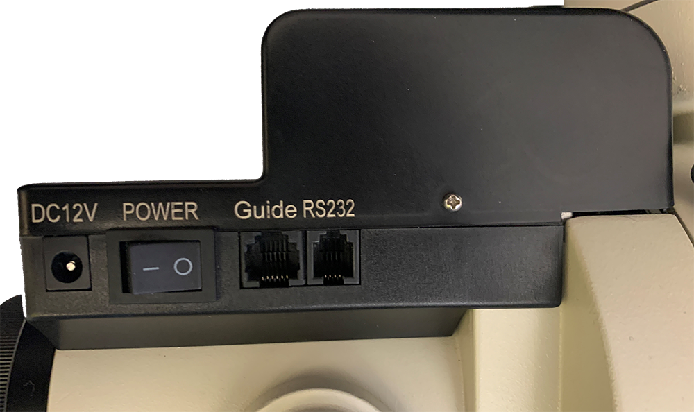
Figure 205: The RS232 port on the iEQ45-Pro mount.
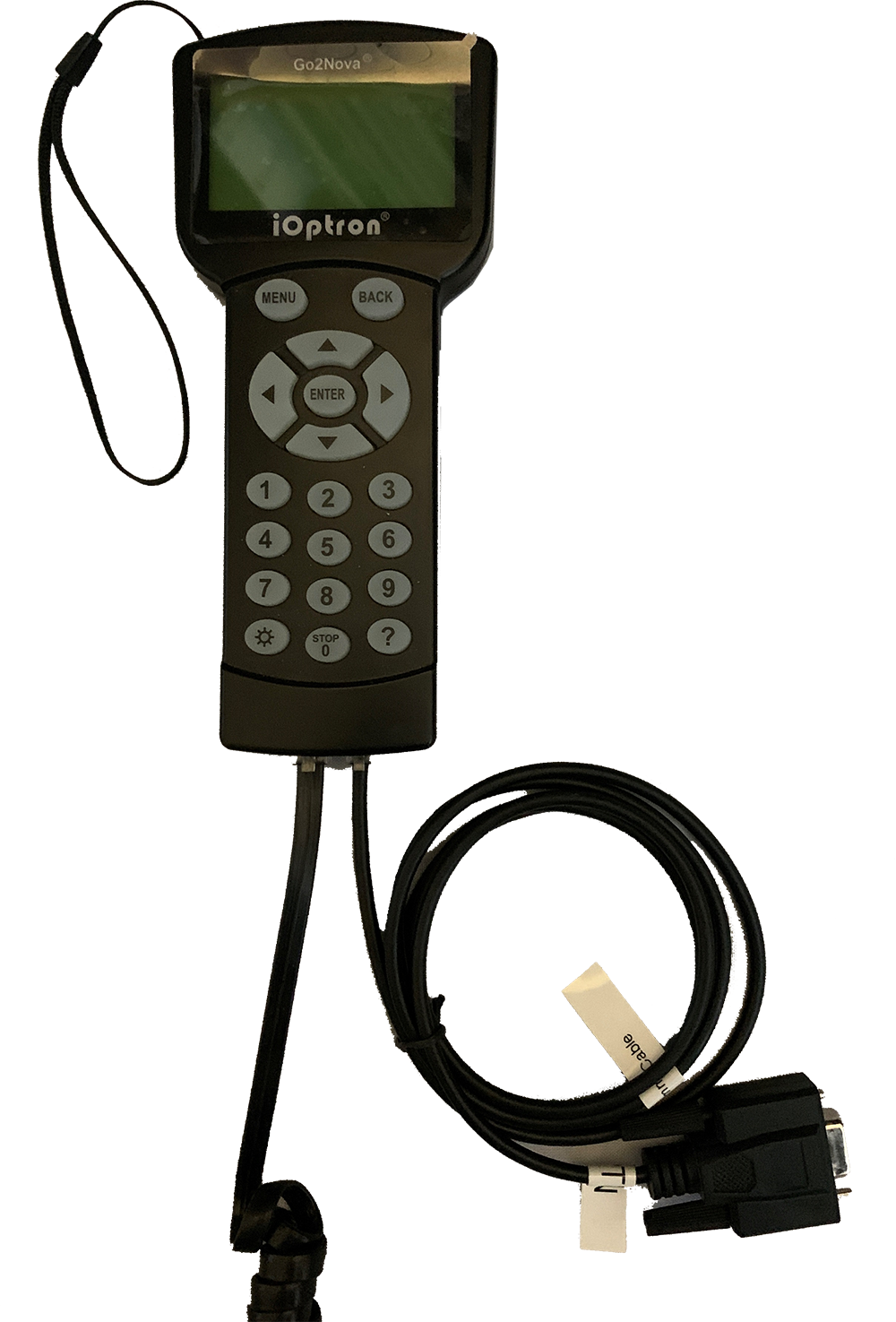
Figure 206: The telescope cable plugged into base of the hand paddle.
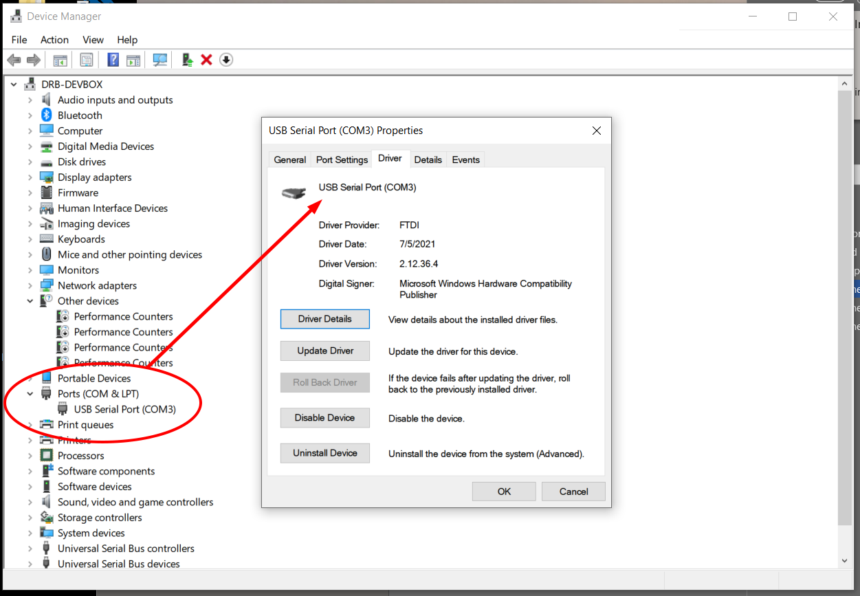
Figure 207: Windows Device Manager showing the iOptron USB Serial Port on COM3.
1. Plug the USB Type B end of the cable into the USB port on the mount (Figure 204).
2. Plug the USB Type A connector into one of the computer’s ports.
3. From TheSky, click Telescope > Telescope Setup.
4. On the Imaging System Setup window, double-click Mount, select your iOptron model mount and click OK.
5. On the Imaging System Setup window, click Mount Setup > Settings and select the name or number of the serial port.
The USB specification limits the cable length to 3 m (15 foot) or shorter USB cable with Type B and USB Type A connectors. Longer USB cable runs require a USB extender, powered USB cable, or USB hub.
(Note that the iOptron USB port was not recognized on macOS during in-house testing. )
1. Plug one end of an Ethernet cable to the Ethernet port on the mount.
2. Plug the other end into a NIC on the local network.
3. Plug the hand paddle into the HBX port.
4. On the hand paddle, press Menu > Settings > Network Options > Wired Status and write record the mount’s IP Address (an example IP address is 192.168.16.254) , and the port number (8080).
5. From TheSky, click Telescope > Telescope Setup.
6. On the Imaging System Setup window, double-click Mount, select your iOptron model mount and click OK.
7. On the Imaging System Setup window, click Mount Setup > Settings and select TCP/IP for the serial port.
8. Enter the IP Address and Port number.
If your mount has a Wi-Fi option as shown on Figure 204, and your computer as a Wi-Fi adapter, TheSky can communicate with it wirelessly.
1. Get the mount’s IP Address from the hand paddle. Press Menu > Settings > Network Options > Wireless Status and write it down (an example IP address is 192.186.16.254) , and the port number (8080).
2. From TheSky, click Telescope > Telescope Setup.
3. On the Imaging System Setup window, double-click Mount, select your iOptron model mount and click OK.
4. On the Imaging System Setup window, click Mount Setup > Settings and select TCP/IP for the serial port.
5. Enter the IP Address and Port number from above.
Once TheSky is configured to communicate with the mount, follow the steps below.
1. Select the Connect command from the Telescope menu.
2. On the Telescope Setup window, select the Location, Date, Time command and verify TheSky’s location, date, time, and time zone settings match the mount’s settings. Click the right pointing green arrow button to update the mount’s settings to match TheSky’s settings if they don’t match.
3. Click the Star Synchronization command (page 398) on the Start Up pop-up menu, then follow the on-screen instructions to complete the initialization.
The iOptron should now be initialized and ready to use.
Settings specific to iOptron mounts can be accessed from the iOptron window. By default, this window appears as a pane on the left side of the Sky Chart and is displayed automatically when a connection to the mount is established. Choose the iOptron command from the Display menu to show this window if it is hidden.
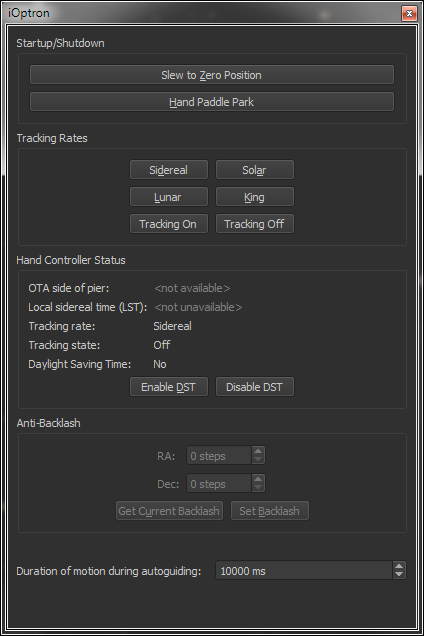
Figure 208: The iOptron settings window.
Use this window to access settings that are specific to your model mount.
These controls provide access to operations that are specific to the iOptron hand paddle.
Click this button to slew the mount to the zero or “home” position. See the iOptron documentation for details about this command.
The iOptron hand paddle offers a Menu > Park Telescope command that slews the mount the park position defined using the hand paddle’s Menu > Settings > Set Park Position command.
Once the park is complete, the hand paddle text reads, “The telescope is parked, please turn off the mount.”
|
|
The iOptron hand paddle park is independent of TheSky’s software park feature (see page 397 for details about TheSky’s software-based park commands). |
iOptron mounts support four different tracking rates:
· Sidereal
· Solar
· Lunar
· King
Also be sure to turn tracking on by clicking the Tracking On button. Click the Tracking Off button to stop tracking at this rate.
These controls can be helpful to double-check that the mount is initialized properly for your site.
|
|
This feature is available for iOptron mounts that support the version 1 command protocol. |
For a German equatorial mount, the optical tube assembly normally resides on the west side of the pier when observing objects on the east side of the meridian. Likewise, the optical tube assembly normally resides on the east side of the pier when observing objects on the west side of the meridian.
However, German equatorial mounts can be oriented such that the counterweight shaft is “above horizontal”. In this orientation, the OTA is on the east side of the pier, and observed objects are on the east side of the meridian. In this orientation “atypical” orientation, synchronizing the mount to a star causes the telescope to think the OTA is on the opposite side of the pier, and subsequent mount slews will end up at the wrong equatorial position. Before synchronizing, orient the mount such that that the counterweight shaft is in a “below horizontal” position, then choose a bright star on the appropriate side of the meridian.
|
|
This feature is available for iOptron mounts that support the version 1 command protocol. |
Displays the local sidereal time that is computed by the hand paddle. The hand paddle’s LST must closely match TheSky’s LST; if they do not, reset the mount’s location, date, and time to match TheSky, as described above. If the LSTs differ by one hour, make sure the hand paddle’s Daylight-Saving Time setting is correct for your site and for the current date.
Shows the hand paddle’s current tracking rate, either Solar, Lunar, King or Custom.
Shows the hand paddle’s current tracking state, either on (the RA motor is rotating at the current tracking rate) or off (the RA motor is stopped).
Shows if the hand paddle’s Daylight-Saving Time option is in effect or not.
Click the appropriate button to enable or disable Daylight Saving Time.
|
|
The backlash options are available for iOptron mounts that support the version 1 command protocol. |
To minimize the effects of backlash between the worm and gear, the hand paddle can be configured to rotate the right ascension or declination axis by a small amount, in the opposite direction of the slew, after a slew is completed. The amount of rotation is defined by the step size in each axis. Use the hand paddle to determine the angular size, in arcseconds, of each step. For example, the Anti-Backlash setup screen on the iEQ30 model states: “One step equals to [sic] 0.11 arc seconds.”
Enter the number of backlash compensation steps for each axis, then click the Set Backlash button to save these values to the hand paddle’s permanent memory.
Click this button to retrieve the current RA and Dec steps from the hand paddle’s permanent memory.
Click this button to save the current RA and Dec steps to the hand paddle’s permanent memory.
Enter the length of time, in milliseconds, the telescope is moved when guider corrections are applied.
